4 Advanced drawing
This chapter describes additional features of xtherion:
- 3D visualization,
- how to import cave maps (with no survey data),
- search and replace,
- maps and atlases,
- overposition with geographical maps,
- exporting data for a database,
- importing survey data processed by other programs.
4.1 Tips and tricks
4.1.1 Survey files
It is possible to open several survey files at the same time. The list of open files is shown in the “Files” control of the controls panel.
move (button)
4.1.2 Rearraging objects in a .th2 file
The “Objects” control of the panel in the map editor contains two buttons, “Move up” and “Move down”, that move the selected object up or down, respectively, in the list of the objects. Essentially, they move the line in the list of the lines that compose the “.th2” file. The “Move to” command allows to specify the line number where to move the selected object.
station names
4.1.3 Station names
This configuration command adds the station names to the output maps:
export map -layout-debug station-names
To change the size of the station names one must add some MetaPost code, using the command code metapost. This is discussed in section 5.4.
split (line)
4.1.4 Breaking a line
To break a line in two at one of its intermnediate points, you must select the point, and in the “Line” control (of the panel) select the action “Edit line | Split line”. If you need to break a line where there is no line-point, you must first insert a new line-point there (action “Edit line | Insert point” of the “Line” control).
When you break a line, xtherion replaces that line with two new lines, one for each of the two line pieces. When you break a line that is part of the contour of an area xtherion does not automatically update the list of lines of the contour (eg, replacing the old line with the two new ones), but maintains the reference to the old line. Therefore the compilation gives an error.
To fix it select the area. The compilation gives you a red error; click on it and xtherion brings up the map editor, with the area that raised the error, selected. Check which of its lines is missing in the scrap. You can read the line ids in the list in the “Areas” control, and each line id is displayed in the status bar when you pass over the corresponding line with the mouse (the line is highlighted light-blue). When you have found the id of the missing line, select it in the “Areas” control, and click the action “Insert” in the same control. Now you can insert the new lines in the list of the area: click on them (in the order) on the canvas. Return to the selection mode pressing the “ESC” key. Finally remove the old line id from the list (action “Delete” of the “Areas” control).
join (.th command)
joins are also affected by line splitting. Since the line id is lost when you split a line, the “join” commands that refer to it are invalidated, and therion gives an error when you compile the project. You must assign id to one (or both) of the new lines and put this id in the “join” command(s). See joining_scraps_together
pillar
4.1.5 Pillars
Pillars are pieces of rock in the middle of the cave map. For example the portion of rock in the middle of a loop. These areas do not belong to the cave, and should not be coloured, but must be “outside” the rendered area that defines the cave passages.
To tell therion that a wall belongs to the contour of a pillar in the middle of the cave, add the option “-outline in” to it. This option specifies that the rock is “inside” the outline (the usual situation is that the rock is outside the outline).
4.2 3D viewer
For the 3D viewer you must have tom (and OpenGL). On Linux you must go into the subdirectory “thtom” and execute “make”. Then copy the contents of the directory “Tom0.2” in the directory of your distribution of Tcl/Tk.
The 3D viewer displays models in the native format, ie, “.xvi”. However (S. Mudrak, 2006-04):
  But we do not develop xtherion model viewer any more.
  Images on the web are from the new therion 3D viewer,
  that we would like to publish in August this year.
As a matter of fact the new 3D viewer is a bit late.
4.2.1 Creating the model
To create the 3D model add the command export model to the configuration file. For example, “export model -fmt therion”. The native format of therion is the one used by the viewer (in xtherion). You can also export the model in other formats:
- “therion”, native format of therion, “.thm”;
- “compass”, “.plt” file;
- “survex”, “.3d” file;
- “dxf”, AutoCad DXF (Drawing Interchange Format) file;
- “vrml”, Virtual Reality Modeling Language;
- “3dmf”, QuickTime 3D metafile.
After compiling you get a file with extension “.thm”. If you do not specify the “-output” option, the default name is “cave.thm”. This file can be viewed with xtherion.
When you export the model in DXF (default name “cave.dxf”), the model is very simple. It contains only three “layer”s: the centerline (CENTERLINE), a triangulation of the walls (WALLS), and the enclosing bounding parallelogram (BBOX). All the symbols and texts that compose the drawing are not exported.
passage_height (point type)
dimension (point type)
The model is generated from the contour of the map, ie, the outlines of the scraps. The height of the passages is computed taking into account points of type “passage_height” and points of type “dimension”, which specify the dimensions of the cave passage in directions perpendicular to the page [thbook 36, thwiki 2]. For instance “point dimension -value 4.0 2.0 m” specifies a point where the passage ceiling is four meters above the centerline and the floor is two meters below [thbook 21]. The units is optional.
4.2.2 Visualization
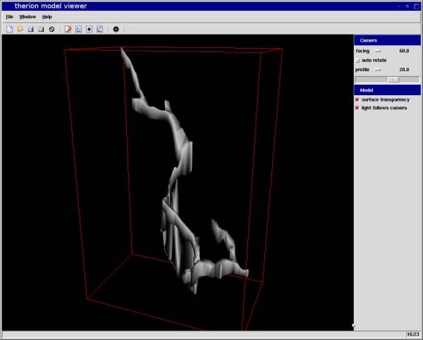
To view the model with xtherion switch into 3D viewer mode (menu “Window | Model viewer”). The window appears as a black area with a red outline of a box. The panel has two controls,
- “Camera” to position the point of view,
- “Model” with two checkboxes for the properties of the model.
The buttons of these controls are rather intuitive:
- there are two selections for the point of view. The first can be set to “facing” (viewing the model frontwise), or to a “north”, “east”, “west” or “south”. The second can be “profile”, “top” (from above) “side” (from the side), “bottom” (from below).
- the slider defines the azimuth of the point of view.
- the “autorotate” checkbox make the model to rotate slowly.
- the “surface transparency” checkbox makes the walls of the cave transparent.
- the “light follows camera” checkbox makes the lighting follow the point of view, so that the model always appear in light.
To view the model you just created select the menu “File | Open” and choose the file with extension “.thm”.
4.3 Importing maps
station (type)
visibility (option)
join (.th command)
therion can import cave maps for which you do not have the suvery data [thwiki 6]. To this aim you need:
- to digitalize the cave map with a scanner;
- for each image to define the position of a (virtual) station. This is the station where the map connects with the rest of the cave.
- to define a “survey” with this station, if it does not appear already in another survey of the cave;
- to create a new scrap into which you import the map image as background;
- to define the scale and the rotation of this image in the scrap: if the image has a scale-bar (eg, the 10 m bar), you can use the two little red squares with it, just like for the cross-sections. Place (drag with the mouse) the squares on the ends of the scale-bar and sets the coordinates to (0,0) and (X m,0) where X is the length of the bar, in meters. Remember that the 'x' coordinate points towards east and the 'y' coordinate points towards north.
- draw the scrap, using the scanned image. Add a point of type “station” for the connection station and set it the option “-visibility off”;
- use the “join” command to connect the scrap to the others.
4.3.1 Example
This example uses fictitious data Suppose to have a map image file, nodata.gif. Create a new map file, nodata.th2, for the scrap with no survey.
In the data file nodata.th define the “survey” nodata with the single virtual station “1”, and “equate” it to a real station of the cave survey. You do not have to define a centerline.
    survey nodata
      input nodata.th2
    endsurvey

    equate 1@nodata 4@s1

    join linea_sx@nodata:0   s1_sxf@s1:end
    join linea_dx@nodata:end s1_dxf@s1:0
In the file nodata.th2 import the image nodata.gif as background. Next create the scrap (id “scrap_nodata”), specify its projection (“plan”) in the “Scraps” control, and use the little red squares to define the scale and the orientation of the scrap.
Add a point of type “station” for the virtual station “1”. Draw the lines of the scrap and all the other symbols and texts. Finally connect this scrap to the others with the “join” command as shown in the above code.
The figure shows the scrap and the final result.
4.4 Search
search
The text editor and the map editor of xtherion have a control for the search of text in the open data file.
4.4.1 Texts
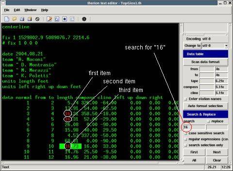
The “Search & Replace” control, in the text editor, performs the search of a word or phrase in the file that is displayed [thwiki 4]. A checkbox allows to specify whether the search should be case-sensitive or not. The search can be limited to a portion of the file, by selecting the portion of search and checking the checkbox “search selection only”.
Write the word (or phrase) you want to search in the text field under the label “search” ad click on the button “First” to get the first instance of the word highlighted in red in the file. With the button “Next” you move to the next instance, which is also highligthed in red. When you have completed the search and there are no more instances of the word to find xtherion makes a beep.
With the button “All” all the instances of the searched word are highlighted in red. With the button “Clear” they revert to green.
If the “replace” checkbox is active, the text of the textfield underneath this checkbox is substituted to the result of the search. The replacement text is highlighted red in the file.
Regular expression are allowed in the in the search text, but the “regular expressions” checkbox must be activated.
4.4.2 Scraps
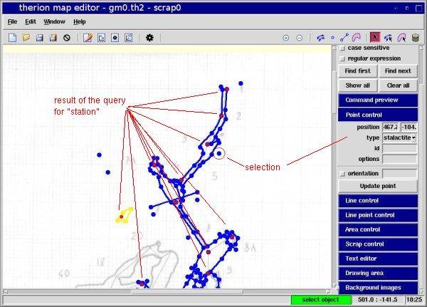
Map datafiles can be searched in the text editor, as they are regular text files, but it is often more convenient to use the map editor. This has the “Search & Select” control that carries out a text search in the open file and highlights the result graphically on the drawing canvas.
The control has a field to write the expression to search. This can be “case-sensitive”, and can also be a regular expression. There are four buttons: “Find first”, “Find next”, “Show all” and “Clear all”. They ae analogous to the similar bottons of the text editor search control.
For example, if you search for the word “station” you get all the points of type “station” highlighted in red in the canvas.
4.5 Maps
To create and export cave maps, therion collects all the informations of the commands of the data files and the configuration file (layout) and make a multilevel drawing. The process is explained in the “Therion Book” [thbook 36-37].
4.5.1 Graphical elements
context (option)
Graphical elements are points (symbols and texts), lines and areas. Each element can be
- visible or invisible (option
-visibility). Only the visible elements are exported in the map. - clipped to the outline or continuing outside of it (option
-clip); - masked because it depends on another alement, that is its context (option
-context); - placed on a specific leyer (option tt{-place}).
visibility (option)
4.5.1.1 Visibility
A graphical element is visible (ie, it appears in the outcome) if
- its
-visibilityis not “off” (it is “on” by default for every element); - it is not hidden due to layout options (
symbol-hide); - it does not depend on a context that has been hidden.
symbol-hide (layout option)
At configuration level (layout) it is possible to hide graphical elements depending on their type. For example, you can use the layout option “symbol-hide line wall” to inhibit the drawing of the cave walls on the map. Other examples are “symbol-hide point cave-station” and “symbol-hide point surface-station”, to hide the stations of the cave surveys and of the surface surveys, respectively.
group
The “group” type defines groups of symbols [thbook 41],
- “group all”
- “group centerline”
- “group cave-centerline”
- “group surface-centerline”
- “group equipment” 5.3
- “group ice” 5.4
- “group passage-fills” 5.3
- “group sections”
- “group sediments 5.4
- “group speleothems” 5.3
- “group text” 5.4
- “group water” 5.3
The option “symbol-hide group all” hides all the elements of the map, except those that are explicitly rendered with the option “symbol-show”. For instance you could use the option “symbol-show line survey” to draw only the stations after hiding all the elements.
clip (option)
4.5.1.2 Clipping
Some symbols are clipped by default to the inside of the map outline:
- the symbols of fillings (“sand”, “mud”, “guano”, …).
- the lines that do not have the
-outlineoption, exceptsection,arrow,label,gradientandwater-flow. - all the areas
Some graphical elements, that are clipped by default, can be extended beyond the outline using the option -clip off.
groups
layer
place (option)
4.5.1.3 Placing
Every graphical element belongs to a layer (or group). The graphical elements are rendered in the cave map following the order of the layers. There are five layers:
- bottom, the lowest layer. It contains only elements that have the option
-place bottom. - default-bottom. It contains the areas.
- default;
- default-top. This contains the
ceiling-stepandchimneyelements by default. - top. It contains the elements that have the option
-place top.
The default layer contains all the elements that do not belong to one of the other layers. The ordering of the graphical elements in a layer follow that of the commands in the input data files. The graphical elements are drawn starting from the last, therefore an element is drawn over those that follow it in the file.
4.5.2 The map construction
The cave map is built in steps:
- the drawing area is filled with the background color (
color map-bg). - if there is the
surfacecommand and the layout optionsurface bottom, the surface image is drawn. - the outline of each scrap of the map is filled with white, so that it can be drawn in the next steps.
- if the layout has the option
grid bottomthe rectangular grid is drawn (with the specified size). - if there is a map with the “map” option
preview below, this is drawn. - for each level of the
mapcommand, starting from the last (the lowest level):
- - the outline of each scrap is filled with the foreground color,
color map-fg. - - the areas of each scrap are rendered, clipped to the inside of the outline.
- - for each scrap all the clipped elements are drawn, following the order of definition (of the layer).
- - the centerline segments are drawn
- - for every scrap all the unclipped elements are drawn, following the order of definition (of the layer).
- - the station points are drawn.
- - all the labels (including
wall-altitude) are written.
- if there is the
preview abovemap, this is drawn with the pecified color,color preview-above. - if there is a surface image and the layout has the option
surface top, the image is drawn. - the grid is drawn if the layout has the option
grid top.
map-header (layout option)
4.5.3 Map header
The contents and the position of the header of themap are configurable. The option “map-comment” allows to insert a comment in the header, for example map-comment “Scale 1:500”.
The option “map-header-bg” can have argument “on” or “off” (default). If it is “on” the header is written on a background which could hide part of the map.
The header position is specified through the layout option “map-header”. This has three arguments, the value of X, the value of Y, and a string that says the type of the reference and can be one of “n”, “ne”, “e”, …, “nw”, “center”, “off”. If it is “off” the header is not written. The other strings specify the position of the lower-left corner of the drawing with respect to the region of the header. Positive X values denote shifts to the right (in meters). Positive Y values denote downward shifts.
statistics (layout option)
The option “statistics” includes or not, in the header informations about the survey statistics. It has an argument that can be a number, or “off” or “all”. The number specifies how many data to write. For example “statistics topo 3” tells to write only the names of the first three surveyors. The value “off” specifies not to write anything, and “all” to write all the data. The statistics are
- “topo”, informations about who did the survey (“centerline” “team” option) and the year. The names are ordered by the length of the surveys. In case of equal length, the order is alphabetical. It is possible to specify explicitly what to write using a layout option “code tex-map” containing the command \def\topoteam{…}
- “carto”, the data of the author of the map;
- “copyright”, copyright informations;
- “explo”, informations on the people that explored the cave (“centerline” option “explo-team”);
- “explo-length”, it can be either “on” or “off”, and it states whether to include the data of the length of explored cave for each explorer;
- “topo-length”, it can be either “on” or “off”, and it states whether to include the data of the length of survey for each surveyor.
author
copyright
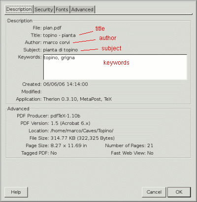
The authors are defined with the scrap option “author”. For example -author 2005 “marco corvi”. The “copyright” are defined similarly (for each scrap). The author names appear after the header “Drawn by:”, the copyright names appear after the copyright symbol ”©“.
4.5.4 PDF options
The “export” command has a few options that refer to the PDF document [thbook 44]:
- “doc-author” specifies the author of the PDF document;
- “doc-keywords”, lists the keywords of the document;
- “doc-subject”, is a short description of the contents of the document;
- “doc-title”, for the title of the document.
For example, you can define a layout with these options, and include it in the “export” command (using the option ”-layout xpdf“),
    layout xpdf
       doc-author "your name"
       doc-keywords "cave, system"
       doc-subject "plan map of cave"
       doc-title "cave - plan"
    endlayout
If you open the PDF document of the map with acroread, under the menu “File | Doc properties”, you can see these properties, as shown in the figure below.
4.6 Atlases
atlas (layout option)
An atlas is a map of the cave, subdivied in pages. It is useful when you need to printout the cave map and the map is larger than the papersize of the printer. In this case you print the map a piece (one page) at a time and paste the pieces together to compose the whole map.
To make an atlas you specify the option “atlas” instead of “map” in the “export” command,
export atlas ...
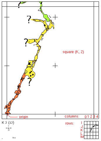
Each atlas page has the coordinates of the page and its number in parethesis. There are also the numbers of the pages to the north, the east, the south and the west, and at the higher and lower levels. The page numbers are omitted if there is the layout option “page-numbers off”.
select (thconfig command)
If the option “title-pages on” is specified, title pages are included for each atlas chapter There are chapters when the configuration file has several “select” commands. For examples the following lines of configuration file produce two atlas chapters, the first with title map7 and the second with title map1,
    select map7@test7
    select map1@s1.test7
origin (atlas option)
The layout option “origin X Y Z m” specifies where the grid origin is placed. For instance, having fixed the geographical coordinates of the cave entrance with the command “fix 1 1529802.9 5089076.7 2214.6” in a survey, if you set “origin 1529802.9 5089076.7 2214.6 m” the lower-left corner of the central square of the grid coincides with the entrance. The option “origin-label” specifies the indices for the grid central square. For example “origin-label K 2” assigns indices (K,2) to the central square, using letters for the rows and numbers for the columns, as in the figure below (made using the option “origin-label K 2”).
The pages of the atlas contain also a 5×5 navigation grid with the cave map in small scale. The central square of this grid corresponds to the map on the page. The size of this navigation grid can be defined with the layout option “nav-size”. For example “nav-size 1 2” states to put three cells horizontally and five vertically.
overlap
The border of the page are zones of overlap with the neighoring pages. They are also links that allow to navigate in the atlas to the nearby pages (by clicking on the relative border). The width of these borders can be defined with the layout option “overlap”. The default is 1 cm.
legend (layout option)
The layout option “legend on” adds a final page with the legend for the map.
Other atlas options concern the dimensins of the pages:
- “page-sutup W1 H1 W2 H2 LM TM units”, where W1 and H1 are width and height of the paper, W2 and H2 are those of the page, and LM is the left margin, TM the upper margin. For example, the default is “page-setup 21 29.7 20 28.7 0.5 0.5 cm”.
- “exclude-pages page_list”, states which pages must be omitted in the output. For example “exclude-pages on 2,4-7,9” leaves out pages 2, 4, 5, 6, 7, and 9. To find the correct page numbers, you can first make an atlas with the options “own-pages 0” and “title-pages off”, and check on it the page numbers you want to omit. When you create the final atlas (without those two options) you specify the same page numbers in the “exclude-pages” option. (The page numbers in the final PDF might be different, but you refer to the numbers you got earlier in “exclude-pages”).
- “nav-factor” sets the scale factor of the navigation grid. For instance the default is “nav-factor 30”.
- “size W H units” sets the size of a cell of the atlas. The default is “size 18 22.2 cm” (good for A4 paper).
- “own-pages N” sets the number of the first page. For example if you specify “own-pages 100” the first page has number 101.
4.7 Topographic maps
topographic map
surface (.th command)
The surface command of the data file is used to position the cave map on a topographic map [thbook 26]. This command takes as argument the filename of an image (in a format supported by therion, such as PNG), or a grid of 3D data.
In the first case the syntax is
     surface
       bitmap filename calibration
     endsurface
Here “filename” is the name of the file with the ground map, and “calibration” is a set of eight values that define the correspondence between two points in the image (pixel units) and the two corresponding points in the map (geographics coordinates, units are meters by default). You need two points to position the cartographic image with respect to the cave map. Infact the image is rotated, scaled and translated (no shear). For example
    surface
      bitmap grigna.png [0 1176 1529079.8 5089914.6 854 186 1529802.9 5089076.7]
    endsurface
In this example the image has size 1900×1176, the coordinate of the entrance on the image are (854,990) [pixels]: X is horizontal, from left to right, Y is vertical downward. In the calibration the Y-axis is considerd upward, therefore instead of 990 there is 186=1176-990. Similarly the upper-left vertex of the image is (0,1176). The size of the pixel is 0.847 in both directions, therefore this vertex has metric coordinates 1529802.9 - 854*0.847 = 1528949.7 and 5089076.7 + 990*.847 = 5089914.6.
In the second case the syntax is
      surface
        grid-units units
        grid x y dx dy nx ny
        grid-flip flip
        data
      endsurface
Here “units” are the units of the grid data. By default it is meters. The grid origin is placed at the map point (x,y). The grid has step (dx,dy) and it has nx nodes horizontally, and ny vertically. The grid data follow: this is the sequence of the altitudes (above see level) at the nodes, starting at the origin and sweeping the grid row-wise from west to east, and from south to north. The “grid-flip” command is optional: it is used when the grid data are given in another order. It can take values “none”, “vertical” or “horizontal”.
It is possible to specify both the image and the altitude grid (S. Mudrak 2005-11-30),
   # surface command for entering surface
   surface
     # grid to specify position of surface
     # grid X-start Y-start X-step Y-step C-columns R-rows
     grid 400080 5419750 10 10 190 68
     # calibrated surface texture - not yet supported in 3D viewer
     bitmap <filename> [calibration-parameters]
     # followed by CxR altitudes matrix
     1520 1530 ...
     ...
     1680 1690 ...
   endsurface
4.7.1 Example
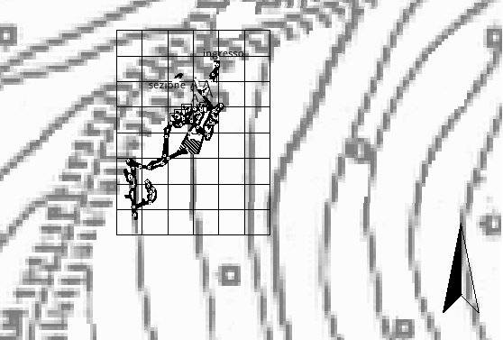
As an example load the surface map file “sovra.png” in the plan map of the example “gm-therion”. Add the following command to the data file
     surface
        bitmap sovra.png [114 107 0 0 88 56 -33 -64]
     endsurface
The values of the calibration have been found from the position of the cave entrance (0,0 in the map) on the groundmap image, and from the scale and scan resolution of the groundmap image.
In the configuration file you need to add to the layout options to include the surface,
      -layout-transparency on \
      -layout-surface bottom \
      -layout-surface-opacity 80
The first one activates the transparency of the cave map (the default “opacity” value is 70). The second option places the surface on the lowest level, the “bottom” one.
The result is shown in the figure below: the example cave is rather small, and it disappears somewhat in the topographic map.
4.8 Database
With therion you can export the survey data in a script with which you can create and populate a database [thbook 49].
4.8.1 Preparing the SQL
The command in the configuration file is
export database -output "filename.sql"
The outcome is a file with SQL commands to create the tables of the database, and commands to populate them with the survey data.
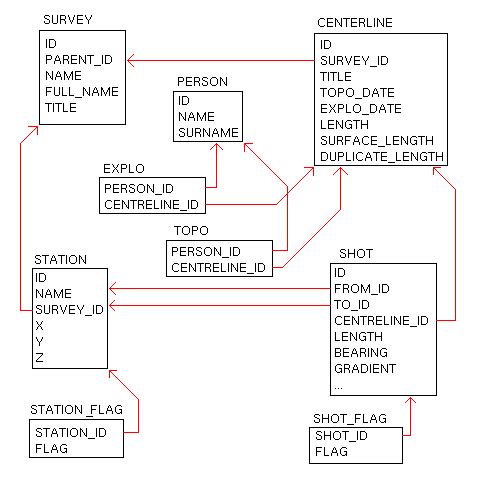
In particular the following tables are created:
- “SURVEY”, for the individual surveys;
- “CENTRELINE”, for the centerlines;
- “PERSON”, for the people;
- “EXPLO”, for the relations person-centerline (as explorers);
- “TOPO”, for the relations person-centerline (as surveyors);
- “STATION”, for the stations;
- “STATION_FLAG”, for station flags;
- “SHOT”, for the centerline shots (the legs);
- “SHOT_FLAG”, for shot flags.
The structure of the database is rather simple as can be seen from the figure above. Nevertheless it is possible to make interesting queries. For example the length that has been surveyed in a given period:
    select sum(LENGTH) from SHOT S, CENTRELINE C
       where S.CENTRELINE_ID = C.ID
          and C.TOPO_DATE between '2004-01-01 and '2004-12-31';
4.8.2 Using the database
For this example we use “sqlite” http://www.sqlite.org. The command to create the database is
sqlite3 filename.db \lt filename.sql
Now you can open a session with the database you just created (command “sqlite3 filename.db”) and at the “sqlite3” prompt you can write the query and see the result:
    $ sqlite3 filename.db
    sqlite> select sum(LENGTH) from SHOT S, CENTRELINE C ... ;
    215.22
    sqlite>.quit
4.8.3 Maintaining the database
There is a problem if you want to import the data of a survey in an existing database (created with data form other surveys). This occurs when you need to add a survey to the set of surveys of a cave or a system.
At present the command “export database” does not have an option to inhibit the generationof the SQL code that creates the tables. Therefore you need to edit the sql file and delete the first lines, namely those that start with the word “CREATE”. The remaining lines populate the database with the survey data. Next you can execute the sql file as before: “sqlite3 filename.db < filename.sql”.
Be careful not to populate twice the database with the same SQL file, otherwise the data are inserted twice, and counted twice. In other words the DB manager does not check that the table records are not repeated.
This workaround is not a solution. There might be name conflicts between the data of the sql script file and the data already stored in the database. If this is the case, the database will end up in a state that is probably not what you expect.
4.9 Importing surveys
Therion can import survey centerline data, produces by other programs and use it in the generation of the maps.
therion cannot use survey data written in survex format. Therion survey data format is slightly different from survex and you cannot import raw survex data. You can however import ”.3d“ data file generated with survex.
4.9.1 Names
import (.th command)
The command for this is “import”. It takes as argument the filename to import and has the following options:
- ”-surveys“ defines how to interpret the station names, with respect to the therion internal name hierarchy. It can be “create” (default), “use” or “ignore”.
- ”-filter“ followed by the prefix string, indicates to drop the prefix from the names of the stations. For example, with ”-filter top.“ the station input name “top.middle.sub.1” is filtered to “middle.sub.1” before inserting into the therion name hierarchy.
The effect of the ”-surveys“ option depends of the level at which the “import” command is located in the survey hierarchy. With ”-surveys use“ therion will try to use existing surveys (and subsurveys) of that level. For example consider the following import of a 3d file with station name “top.middle.sub.1”,
   survey top
     import file.3d -surveys use -filter top.
     survey middle
       survey bottom
         ...
       endsurvey bottom
       ...
     endsurvey middle
   endsurvey top
therion will first filter the prefix top, thus leaving the name “middle.sub.1”. Next therion will try to use the survey middle, and since there is such a survey at the level of “import”, it changes the name to “sub.1@middle”. Then it will try for a subsurvey of middle named sub, but it does not find it, so the name stays as it is (if found the name would have become “1@sub.middle”).
With the value “create”, survey names to fit the names of the stations are created and inserted in the therion hierarchy. For example, with the station name “top.1” therion creates a survey top and refers to the station as “1@top”.
With ignore surveys are not created.
The “scrap” command has an option for name prefixes and suffixes, ”-station-names prefix suffix“. For example ”-station-names top. []“ says to prefix all the names in the scrap with “top.” and to suffix with the empty string. In this case the point option ”-name 1“ is interpreted as if the name were “top.1”.
It is also possible to add suffixes. For example with ”-station-names [] @top“ the point option ”-name 1“ gives the name “1@top”.
Some remarks.
- It is important to put the “import” command inside a “survey” command. Infact in Therion stations and shots must be inside a survey container.
- It is possible to import a station twice;
theriondoes not give any warning. If this were not the case, one would not be able to work with local and global .3d file without modifying the data files (ie, commenting “import” command on local level, when a global level “import: is present). - It might be necessary to add empty “survey” commands after the “import” command, if the option ”-surveys use” is specified, so that survey names are defined in the therion survey hierarchy, that fits the names used in the drawings.
4.9.2 Importing a .3d file
The following examples has a piece ho centerline in a survex data file, and another piece in a therion file. The configuration file has the command “source global.th”, and the file global.th organizes the data. Everything is contained in the survey middle. Therefore the station names from the survex 3d file are filtered out the top. prefix, and the survey hierarchy is used. The survey middle has a subsurvey bottom and includes a scrap file middle.th2. There is an equate command to equate the two stations, sub.2@middle from the 3d survex file and 1@sub.bottom.middle from the therion data file. Finally there are the wall lines “join” commands.
   survey global
     import global.3d -filter top. -surveys use

     survey middle
       survey bottom
         input bottom.th
       endsurvey bottom
       input middle.th2
     endsurvey middle

     centerline
       equate 1@sub.bottom.middle sub.2@middle
     endcenterline

     join m1_sx@middle:0   b2_sx@bottom.middle:end
     join m1_dx@middle:end b2_dx@bottom.middle:0

   endsurvey global
The survex source file, from which the 3d file is generated, is
   *begin top.middle.sub
   * export 2
   ...
   *end top.middle.sub
Notice that the station “2” of this centerline must be referred, at level global, as sub.2@middle because the prefix top. has been dropped, and middle has been used in the survey hierarchy.
The therion survey data file bottom.th is
   survey sub
     centerline
       ...
     endcenterline
   endsurvey
   input global_bottom.th2
Notice that the scrap is inserted at the level {bottom.middle.global} of the survey hierarchy. Therefore the “join” commands refer to the wall lines with the suffix @bottom.middle (the commands are located in the global level). Similarly the station “1” in this centerline is properly referred, at level global, as 1@sub.bottom.middle.
The scrap file bottom.th2 has the form
   scrap scrap1 -projection plan -station-names [] @sub -scale [...]
     ...
     point 419.0 610.0 station -name 1
   endscrap
The option “-station-names” says that the point written with “-name 1” has name 1@sub. As this file is included at level bottom.middle.global, the level global refers to this point as 1@sub.bottom.middle.
The scrap file middle.th2 has the form
   scrap scrap1 -projection plan -station-names sub. [] -scale [...]
     ...
     point 622.0 440.0 station -name 2
   endscrap
In this case the point written with “-name 2” has name sub.2. As this file is included at level middle.global, the level global refers to this point as sub.2@middle.
The data in the map legend might come out incorrect as the “.3d” file refers to the whole cave. Wookey asked how to override the value of the “cavelength” (2006.09.20). S. Mudrak reply
Just add lines like this to your layout:> > code tex-map > \topoteam{Your team.} > \cavelength{1000\thinspace{}ft} > \cavedepth{300\thinspace{}m} > endcode >>
4.9.3 Importing a .plt file
If you process your survey data with Compass 12 you can either transform your .dat files in therion .th data files with a simple script, or you can import .plt files in therion.
For example suppose to have the following “example.dat” file (or the corresponding “example.plt” file)
         SURVEY NAME: first.dat
         SURVEY DATE: 7 24 2006  COMMENT:
         SURVEY TEAM: ...
         ...
         FROM  TO  LENGTH BEARING  INC   LEFT  UP    DOWN  RIGHT FLAGS COMMENTS
            1  2   10.00   90.00   0.00  1.00  2.00  0.00  1.00
            2  3   10.00  180.00   0.00  1.00  2.00  0.00  1.00
            3  4   10.00   90.00   0.00  1.00  2.00  0.00  1.00
            4  5   10.00  180.00   0.00  1.00  2.00  0.00  1.00
         ...
You can write a .th data file that imports the .plt file (and inputs the .th2 map file),
    survey example
    import example.plt
    input example.th2
    endsurvey
The station point commands in the map file “example.th2” can refer to the station names in the .plt file as, for instance, “point 593.0 241.0 station -name 4”.
4.A PDF atlases
atlas (layout option)
This appendix describes how therion creates the PDF files for atlases. therion defines several TeX macros, and at the end it invokes the TeX command “ \dopage ” to generate the output page.
The variable used writing the page are
- \mapbox , the box with the map drawing. It has size size_width + 2 * overlap and size_height + 2 * overlap .
- \navbox , the box for the navigation grid. It has size size_width * (1 + 2 * nav_size_x) / nav_factor and size_height * (1 + 2 * nav_size_y) / nav_factor .
- \pointerE \pointerW \pointerN \pointerS , contain the numbers of the pages to the east, west, north and south (or a value 0 if the page is missing);
- \pagenum is the number of the current page;
- \pagename is the map name;
- \pagelabel is the label of the page. It is specified by the layout options “origin” and “origin-label”.
Other global variables are:
- \hsize
- \vsize
- \ifpagenumbering
Finally therion uses the macros
- \showpointer#1 , to display one of the cardinal pointers;
- \showpointlist#1 for \pointerU and \pointerD ;
- \processpointeritem#1|#2|#3\endarg , for the formatting. It expands to a hbox with the suitable link: \hbox{\pdfstartlink attr {/Border[0 0 0]} goto name {#3} #2 (#1)\pdfendlink}
- \size[#1] is used to change the font size;
- \rm \it \bf \ss \si are used to change the font style; font;
- insertmap inserts the drawings.
Other variables managed by therion and that can be used are those settable through layout options:
- \explotitle \exploteam \explodate
- \topotitle \topoteam \topodate
- \cartotitle cartoteam \cartodate
- \comment
- \copyright
- \cavelength \cavelengthtitle
- \cavedepth \cavedepthtitle
- \atlastitlepage is a combination of these
- \iflegend \legendtitle \insertlegent e \formattedlegend che combina queste tre;
- \ifnortharrow \northwarrow
- \ifscalebar \scalebar
At ths point we can analize the definition of \dopage contained in the therion source file “tex/therion.tex”. The structure, commented on the side, is shown in the figure below in which the vboxes are blue and the hboxes are red.
   \def\dopage{%
     \vbox{%                           +-- global vbox
       \centerline{\framed{\mapbox}}         +-- center mapbox
       \bigskip                              +-- a space
       \line{%                               +-- "navigation" line
         \vbox to \ht\navbox{                      +-- vbox high as the "navbox"
           \hbox{\size[20]\the\pagelabel                 +-- label
             \ifpagenumbering\space(\the\pagenum)\fi     +-- number
             \space\size[16]\the\pagename}               +-- name
           \ifpagenumbering
             \medskip                                    +-- spaec
             \hbox{\qquad\qquad                          +-- pointers hbox
               \vtop{%
                 \hbox to 0pt{\hss\showpointer\pointerN\hss}
                 \hbox to 0pt{\llap{\showpointer\pointerW\hskip0.7em}%
                   \raise1pt\hbox to 0pt{\hss$\updownarrow$\hss}%
                   \raise1pt\hbox to 0pt{\hss$\leftrightarrow$\hss}%
                   \rlap{\hskip0.7em\showpointer\pointerE}}
                   \hbox to 0pt{\hss\showpointer\pointerS\hss}
               }\qquad\qquad
               \vtop{
                 \def\arr{$\uparrow$}
                 \showpointerlist\pointerU
                 \def\arr{$\downarrow$}
                 \showpointerlist\pointerD
               }
             }
           \fi
           \vss                                         +-- vertical space
           \ifscalebar\scalebar\fi                      +-- scael-bar
         }\hss                                      +-- horizontal space
         \box\navbox                                +-- navbox
       }
     }
   }
