MetaPost
…is code to define what the labels and cave symbols in pdf and svg outputs look like.
(Add another metapost links here)
pstoedit translates PostScript and PDF graphics into other vector formats, Metapost format too.
TUG's listing of MetaPost on the Web
MetaPost tutorial, Robert Špalek, česky
Many interesting MetaPost examples, gallery what is possible to do with MP
Page with many links to Metapost documentation and examples
Learning METAPOST by Doing, André Heck (pdf)
Loria: The Metafun manual, Hans Hagen, 2017 (pdf)
or: Pragma: The Metafun manual, Hans Hagen, 2017 (pdf)
Puzzling graphics in METAPOST, Hans Hagen (pdf)
Many nice examples
Many links from Michio Matsuyama, but you have to copy the text and open it as html file
Previewers
Online previewer Java based MetaPost Editor and Previewer (MEPer)
If you are brave Marco has written more than I ever wanted to know here Therion by Examples Metapost and here - Chapter 7
How to create metapost for new symbols
Adapted from advice by Nikita Kozlov and Martin Sluka
- Create a new symbol with your favorite vector graphics editor,
- Save results to .eps format, and then
- Use pstoedit to convert the .eps to metapost,
- Adapt the code to work with Therion (Refer to section 7.4 of Marco Corvi's Therion by Examples), then
- Compile a test map and admire your work.
A limitation is that pstoedit converts only to polylines. It does not create 'curves' or other more sophisticated Metapost entities. It is enough to create user symbol for a tree for example.
Another way is to draw your symbol on graph paper and then create Metapost code for straight or smooth curved lines.
Both approaches will in due course require you to learn some Metapost!
You may check the very basic tutorial of Metapost here:http://meeting.contextgarden.net/2008/talks/2008-08-22-hartmut-metapost/mptut-context2008.pdf
Implementing redefined metapost examples (Bruce Mutton)
These examples show how redefined symbols like those below can be used, and includes a redefinition of Atlas so that it includes a north arrow on each page, and a redefinition of the continuation symbol so that it displays the associated text.
How to get Therions MetaPost code (and Tex code)
You can use this code as a starting point to make your own customisations.
You can either start with the unadulterated source code (perhaps the best way, and as described here) or you can use the code that has been updated with any modifications already present in your current setup (often useful as well if you want to see the end result of your definitions and re-definitions)- as described below.
You need to run Therion in debug mode (command line -d option)  to tell it to produce and retain a folder with interim outputs (not to be confused with layout-debug which can produce 2D outputs with station names, scrap names, intermediate scrap distortions etc).
The folder produced is called thTMPDIR
It contains;
- data.mp = a dump of all the metapost code used by Therion
- data.tex = a dump of all the tex code used by Therion
and perhaps less usefully…
- th_texts.tex = ascii dump of all tex variables
- th_legend.tex = similar dump of the legend
- and much more…
Skim through data.mp and data.tex to find definitions and snippets of code that you'd like to edit.
Copy these to a code-tex or code-metapost block in a layout in one of your *.th or thconfig-*.* files, and make your edits.
The files produced in thTMPDIR will now reflect the code you have entered in your layouts.
By the way, you might be able to use the following to track down errors in metapost code (or in scrap drawings).
faq#how_to_find_where_a_metapost_error_is_occurring
Symbol Sizing and Positioning
On Sun, Feb 7, 2010 Bruce wrote:
Is u (and v w for that matter) intended to correspond to a
particular drawn entity size in the finished pdf, or are they just
arbitrary variables for which one can calculate the value of, using
the code in the initialise definition?
Bruce
u allows nonlinear scaling of symbols depending on scale. The macro initialize assigns a fixed value to 'u' which will be used in pdf for that scale. On average, diameter of point symbols is (or is intended to be) 1u in the output.
v and w behave differently (v could be used e.g. for some area fills with decreasing distance among symbols for smaller scales but only up to a certain threshold, then bigger distance again; w is almost constant). Currently they are not (or perhaps only occasionally) used in symbols design.
In the beginning we wanted to do some sort of optimization of values assigned to u, v, w but did not manage to do it so far. It would be useful if somebody could test alternative values (and alternative breaks for map scale in the initialize macro) for various scales and various styles of map drawing (lot of symbols vs. sparsely filled map). Good setup of these values could improve map appearance substantially.
Cheers, Martin
Refer to the section New Map Symbols, Point Symbols in The Therion Book.
If you want your custom point symbol to be able to be aligned, rotated or scaled by users according to options set in th2 drawing files, then your T:= identity… line will need include those keywords and the variables parsed in the symbol def statement. A number of the point symbol examples below do not, possibly intentionally preventing those symbols from being aligned, rotated or scaled respectively.
- Symbol coordinates (0u, 0u) are the origin point for that symbol. This is the place in the symbol drawing that corresponds exactly to the point symbol location that you will draw in a scrap with XTherion.
- Your symbols should generally be defined so that they fit within the size range -0.5u to +0.5u in both x and y axes, although you can use larger or smaller values in either dimension. This is because we generally want the map symbols to be about ‘u’ in size.
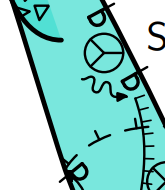
This image is a symbol that has been defined with maximum x and y coordinates, supposedly, of 0.7u, both positive and negative. The insertion point is at the intersection of the cross hairs, and the pdf has been exported with a rotate value of 15 degrees. It has been overlaid with some code that highlights the origin and alignment loci, and unit symbol size, u, as described below.
 at the intersection of the cross hairs, pdf exported with rotate value of 15 degrees")
The symbol alignment option relies on the definition of a U: variable, otherwise your symbol will cause an error and stop Therion if a user sets an alignment option other than centre. The U: variable is depicted by the light blue box.
- U: is a scaling factor for alignment parameters, such as right, top or top-right.
U: defines the size of the x horizontal (left-right) and y vertical (up-down) offset when a symbol is aligned, so the x and y components of U: should be set to be around the maximum absolute value of x and y symbol coordinates, respectively. ie for a symmetrically placed symbol who’s perimeter will just touch the insertion point, set U:=(0.5x symbol width, 0.5x symbol height).
- If a U: component is smaller than a maximum corresponding symbol coordinate, an aligned symbol will overlap the insertion point.
- If a U: component is larger than a maximum corresponding symbol coordinate, an aligned symbol will have a gap from the insertion point.
- If your symbol has its greatest dimension on a diagonal, then you should increase the U: components accordingly, to avoid unintentional drawing overlaps for aligned symbols.
As one 'use case' for aligning symbols is to enable them to be placed ‘near’ to another symbol, and be always positioned appropriately at a variety of output scales, I am going to suggest that U: components for user friendly point symbols should always be just a little greater than half the symbol dimension. ie the light blue box should enclose the symbol. That way, an aligned symbol can always leave a pleasing small gap from its insertion point.
When writing a new point symbol and testing that it aligns and rotates nicely, it can be a bit tricky to figure out where the origin, insertion point, and alignment loci are located. So I have written some code that you can temporarily place inside a symbol, to get a visual representation of how well placed its origin and alignment loci are with respect to its insertion point, and of its size compared to the nominal default size of u.
Here it is inserted into an electric light symbol definition. The code is between the lines with % % %. It creates a green insertion point, a red origin point that represents the (0u, 0u) origin of the symbol, a light blue rectangle that represents the loci of the alignment options (left, top-left etc), and a grey unit symbol size. Note that this code requires that T:= … rotated BEFORE aligned. If your symbol uses T:= … aligned BEFORE rotated, then the code needs to be modified slightly.
After writing the code, I realised that this symbol was in fact larger than 0.7u in the y direction, therefore the U: variable is not tall enough, the symbol is not centered around around its (0u,0u) coordinates (which might be OK if you want the space below the luminaire to be part of the 'symbol') and it is just a bit (but probably acceptably) larger than u in size!
   def p_u_electriclight (expr pos,theta,sc,al) =
      U:=(0.7u, 0.7u);
      % Reduce size of the symbol.  The default size is too big.
      interim defaultscale:=0.4sc;
      T:=identity rotated theta aligned al scaled defaultscale shifted pos; %corrected to rotate THEN align

      % % %  SYMBOL PARAMETER INDICATOR (origin, insertion, alignment box, u box)
      % Placing this code directly after T:= identity line will put the indicators under the symbol
      % Placing this code immediately before enddef will put the indicators over top of the symbol
      % Before use you need to correctly assign the parsed variable aliases in the next two rows from the def statement above
	  rotation:= theta;               %set this to the third parsed variable (ie theta)
	  pair alignment; alignment:= al; %set this to the last parsed variable (ie al)

      % show symbol origin, (0,0) red
          thdraw fullcircle scaled 0.15u withpen PenD withcolor red;
      % show symbol insertion point, (0,0) green
          thdraw fullcircle shifted -(xpart alignment * xpart U, ypart alignment * ypart U) rotated -rotation withpen PenD withcolor green;
      % show U alignment box light blue
          q:= (xpart U, -ypart U) -- (xpart U, ypart U) -- (-xpart U, ypart U) -- (-xpart U, -ypart U) -- cycle;
          thdraw q shifted -(xpart alignment * xpart U, ypart alignment * ypart U) rotated -rotation withpen PenD withcolor 0.5[blue,white];
      %	show u box grey
          thdraw unitsquare scaled u shifted (-0.5u, -0.5u) withpen PenD withcolor 0.2[black,white];
      % % %

      pickup PenC;
      thdraw fullcircle scaled 0.5u shifted (0.0u, 0.7u);
      thdraw (-0.5u, -0.6u) -- (-0.5u, 0.0u);
      thdraw (-0.5u, 0.0u) .. (-0.35u, 0.55u) .. (0.0u, 0.7u);
      thdraw (0.0u, 0.7u) .. (0.35u, 0.55u) .. (0.5u, 0.0u);
      thdraw (0.5u,0.0u) -- (0.5u, -0.6u);
      thdraw (-0.7u, -0.6u) -- (0.7u, -0.6u);
  enddef;
Here is an example with the above point symbol that has been redefined with three different U: settings, and inserted with -align top-right. On the left, U:=(1.0u, 1.0u) [U/u=1.4], in the centre, U:=(0.7u, 0.7u) [U/u=1.0], on the right, U:=(0.5u, 0.5u) [U/u= 0.7]. Note that the alignment, top-right, is relative to the local coordinate system in the scrap, not necessarily to the output page coordinate system. In these examples it does match the output page orientation, because the scrap has 'north up'.

The smudgy line is intended to represent an object that the alignment is intended to avoid, ie a wall. You can see that U: = symbol dimension is OK, but U:= smaller than symbol dimension is probably what most users would want to avoid.
I'm going to suggest that the best values for U: components are between [U/u=1.0] to [U/u=1.2]
An here are some examples with a slightly improved U: variable, with the symbol aligned top-right and oriented 30 degrees, and the output rotated 15, 105, 195, 285 degrees.

And one last example, using point water, with the above code added, that demonstrates how align is related to scrap coordinates rather than the output coordinates.

Bruce
Setting pen thicknesses
This can be used to set a minimum pen thickness, so that all other pens take their sizes relative to that pen thickness. This can be useful for publications that mandate a specific pen width, which can be harder to control with scaling. (This can be done by setting the “u” value, but that causes all symbols to be scaled too.)
code metapost
  def minimumpen = 0.18pt enddef;
  def PenA = pencircle scaled (minimumpen*1/0.35) enddef;
  def PenB = pencircle scaled (minimumpen*0.7/0.35) enddef;
  def PenC = pencircle scaled (minimumpen*0.5/0.35) enddef;
  def PenD = pencircle scaled (minimumpen) enddef;
  def PenX = pencircle scaled (minimumpen*1.2/0.35) enddef;
endcode
Adding custom styled labels at any point/linepoint
Therion does not offer any way to add custom styled labels to inputs - labels are created by various dedicated point symbols. Although you can call some of the internal macros to produce labels, it can be difficult to work out exactly what macro names to call to get it to align correctly, and certain features, such as setting the scaling, require you to modify the TEX rather than the MetaPost.
This function simplifies it all. Add it once, and then any of your custom points can call it to add a label.
code metapost
  vardef create_styled_label (expr plaintext,P,R,S,A,defaultstyle)=
    save textsize, style, thetext;
    string textsize;
    if S = 0.5:
      textsize:="\thtinysize";
    elseif S = 0.7:
      textsize:="\thsmallsize";
    elseif S = 1.4:
      textsize:="\thlargesize";
    elseif S = 2:
      textsize:="\thhugesize";
    else: % normal is 1
      textsize:="\thnormalsize";
    fi;
    if known ATTR_labelstyle:
      style:=scantokens(ATTR_labelstyle);
    else:
      style:=defaultstyle;
    fi;
    picture thetext;
    thetext:=thTEX("\thframed {" & textsize & " \thfb " & plaintext & "}");
    if A = (-1,1):
      p_label.ulft(thetext,P,R,style);
    elseif A = (0,1):
      p_label.top(thetext,P,R,style);
    elseif A = (1,1):
      p_label.urt(thetext,P,R,style);
    elseif A = (-1,0):
      p_label.lft(thetext,P,R,style);
    elseif A = (1,0):
      p_label.rt(thetext,P,R,style);
    elseif A = (-1,-1):
      p_label.llft(thetext,P,R,style);
    elseif A = (0,-1):
      p_label.bot(thetext,P,R,style);
    elseif A = (1,-1):
      p_label.lrt(thetext,P,R,style);
    else:
      p_label(thetext,P,R,style);
    fi;
  enddef;
endcode
Call it like this:
create_styled_label(text, position, rotation, scaling, alignment, style);
Style meanings:
- 0 = basic label
- 1 = label with a dot marker
- 2 = semi circle up
- 3 = semi circle down
- 4 = semi circle up and semi circle down
- 5 = circle
- 6 = box
- 7 = basic label with extra offset
- 8 = supposed to be a filled label, but doesn't seem to work except with q-marks
There are also some constants like p_label_mode_label which can be used instead if you prefer (and you trust that they will never change). Search the Metapost debug output for these.
Each symbol can individually override its label styling by setting the “-attr labelstyle 6” option - the function will check for it, and use that other style if an option is selected.
For an example of code making use of this function, see Rope lengths below.
If you want to add custom label styles, you need to call “thelabel.suffix(thetext,position)” with the right alignment suffix, save the return value in a variable called “lab”, then call “process_label(position,rotation)”. After that, you can check “bbox lab” to get the bounding box of the text label as a path which can be used to draw the decoration. You can temporarily (“interim”) set the internal “bboxmargin” variable to make the bounding box larger than the text, to create some padding between the text and your ornamentation. You should use “begingroup+endroup” within a “def” when using the “interim” operator to make sure it gets reset correctly afterwards, or use a vardef instead of a def.
Use “rotatedaround (position,rotation)” when drawing the ornamentation to make sure it gets rotated and aligned the same as the label. Note that this applies the rotation around the point position, so alignment and rotation at the same time is weird. This is the same with regular labels though - known Therion bug - so at least this is consistent with Therion itself.
Since this will require setting the suffix correctly for both the regular label styles and the custom label styles, there ends up being a lot of duplicated code. It is easier to store the suffix name as a string which can then be extracted with scantokens when calling the appropriate macro, which is what the example code below does. The custom decorations are specified using a style number starting from 100, so as not to clash with the numbers used for Therion's internal label styles.
code metapost
  vardef create_styled_label (expr plaintext,P,R,S,A,defaultstyle)=
    save textsize, style, thetext, sufx, athick;
    string textsize;
    if S = 0.5:
      textsize:="\thtinysize";
    elseif S = 0.7:
      textsize:="\thsmallsize";
    elseif S = 1.4:
      textsize:="\thlargesize";
    elseif S = 2:
      textsize:="\thhugesize";
    else: % normal is 1
      textsize:="\thnormalsize";
    fi;
    if known ATTR_labelstyle:
      style:=scantokens(ATTR_labelstyle);
    else:
      style:=defaultstyle;
    fi;
    picture thetext;
    thetext:=thTEX("\thframed {" & textsize & plaintext & "}");
    % store the alignment suffix as a string, it will be turned back into a suffix with scantokens
    string sufx;
    if A = (-1,1):
      sufx:="ulft";
    elseif A = (0,1):
      sufx:="top";
    elseif A = (1,1):
      sufx:="urt";
    elseif A = (-1,0):
      sufx:="lft";
    elseif A = (1,0):
      sufx:="rt";
    elseif A = (-1,-1):
      sufx:="llft";
    elseif A = (0,-1):
      sufx:="bot";
    elseif A = (1,-1):
      sufx:="lrt";
    else:
      sufx:="";
    fi;
    if style >= 100:
      % create the label, passing the alignment as a suffix
      lab:=thelabel.scantokens(sufx)(thetext,P);
      % process_label looks for a variable called "lab"
      process_label(P,R);
      % define all the different ornamentations that you want
      if style = 100:
        pickup PenA;
        athick:=(xpart (lrcorner PenA)) - (xpart (llcorner PenA));
        % make bounding box measurements temporarily be larger than the object being measured
        % "interim" modifies internal variable, must be inside vardef or def+begingroup to make
        % sure it gets reset to default correctly afterwards
        interim bboxmargin:=5athick;
        % rounded rectangle
        % rotating around P is undesirable when alignment is also used, but this is what regular labels do
        draw ((bbox lab) smoothed 5athick) rotatedaround (P,R) dashed evenly;
      fi;
    else:
      % create the label, passing the alignment as a suffix
      p_label.scantokens(sufx)(thetext,P,R,style);
    fi;
  enddef;
endcode
Replacing legend drawings for existing symbols
When defining a new symbol, you will normally want it to appear nicely in the legend. By default, Therion puts a single point in the centre for point symbols, and a wavy line for line symbols, and a filled rectangle for area symbols. Normally this is fine, but sometimes it does not show off all of the features that you would like to. With custom “u” symbols (p_u_* and l_u_* and a_u_*), Therion creates a default p_u_*_legend macro, which you can choose to override with your own. When drawing the legend, it runs those macros. You can therefore design the legend item yourself. Typically, these are drawn using coordinates from 0 to 1 in the x axis and y axis, with “inscale” scaling them to fit perfectly inside the legend.
This is an example of how Therion calls it:
beginfig(164);
clean_legend_box;
p_u_foo_legend;
draw_legend_box;
endfig;
When you define a new version of an existing symbol (such as p_anchor_MY), it does not work that way. Instead, the MetaPost contains hardcoded calls to the macros, with hardcoded points or paths defined inline, not via macros and variables. These points and paths can be seen in the binary source as being tied to the specific symbols (most symbols use the same few default values, but a few have their own special ones). It ends up looking like this:
beginfig(161);
clean_legend_box;
drawoptions();
p_anchor((0.5,0.5) inscale,0.0,1.0,(0,0));
draw_legend_box;
endfig;
You can detect this default coordinate in your point/line symbol code, and respond differently. But it is entirely possible for a legitimate point in your survey to match “(0.5,0.5) inscale”, and you will end up randomly converting a real point into a special legend version. This approach is therefore not recommended.
There is no other way to ask “is this code running inside the legend” since there is no variable that says that the legend has started.
However, you can rewrite the clean_legend_box macro to store a flag, which you can check in your point code to see if it is running inside one of those legend sections. Legends are always created as the last step, so even though that flag will get left forever, it will not be mistaken in non-legend code.
boolean p_anchor_MY_inlegend;
p_anchor_MY_inlegend:=false;
% store the original clean_legend_box
let p_anchor_MY_legend_box = clean_legend_box;
% redefine clean_legend_box to store the flag, then run the original
def clean_legend_box =
  p_anchor_MY_inlegend:=true;
  p_anchor_MY_legend_box;
enddef;
def p_anchor_MY (expr P,R,S,A)=
  if p_anchor_MY_inlegend:
    % this is the legend - make sure the function works normally again
    p_anchor_MY_inlegend:=false;
    % draw a pretty legend
    p_anchor_MY((.7,.3) inscale,270,1,(0,0));
  else:
    % ... do the regular stuff
  fi;
enddef;
While this does run the risk that the Therion code may change so that the macro cannot be replaced in this way, for now it appear to be the most reliable way to create custom legend items for these symbols. Use it at your discretion (it is used in some of the examples below).
General Symbol Examples
For example; centrelines, water, point altitudes
Point Symbols
Define a user point symbol for a stalagmite boss

def p_u_boss (expr pos,theta,sc,al)=
  T:=identity aligned al rotated theta scaled sc shifted pos;
  pickup PenD;
  p := (0.08u,0.25u)..(0,0.29u)..(-0.08u,0.25u);
  q := (0.16u,0.5u)..(0u,0.58u)..(-0.16u,0.5u);
  for i=0 upto 9:
   thdraw p rotated 36i;
   thdraw q rotated 36i;
  endfor
  p := fullcircle scaled 0.15u;
  thdraw p;
enddef;
Define an entrance symbol as a theta inside a diamond

def p_entrance_MY (expr pos,theta,sc,al)=
  U:=(.2u,.5u);
  T:=identity aligned al rotated theta scaled sc shifted pos;
  path p;
  p = (-.3u,-.25u) -- (-.2u,-.25u){dir 135} .. (0u, .25u) .. {dir 225}(.2u,-.25u) -- (.3u,-.25u);
  thdraw p withpen PenA;
  thdraw unitsquare scaled u shifted (-0.5u,-0.5u) rotated 45 withpen PenD;
enddef;
Define a user point symbol for a single large irregular block

def p_u_block(expr pos,theta,sc,al) =
  T:=identity aligned al rotated theta scaled sc shifted pos;
  path p q;
  p := (2.3u,0.9u)--(0.65u,1u)--(-0.9u,0.6u)--(-2.15u,-0.1u)--(-2.35u,-0.25u)--(-2.5u,-0.5u)--(-2u,-0.65u)--(-0.75u,-0.65u)--(0.6u,-0.7u)--(1.1u,-0.5u)--(2.1u,-0.15u)--cycle;
  pickup PenB;
  thdraw p;
  % The following line uses the code from Colour Dependant Visualization of Symbols by Bruce Mutton
  if known colour_block_bg: thfill p withcolor colour_block_bg; else: thfill p withcolor (0.75,0.75,0.75); fi;
  q := (-2.5u,-0.5u)--(-2u,-0.65u)--(-0.75u,-0.65u)--(0.6u,-0.7u)--(1.1u,-0.5u)--(2.1u,-0.15u)--(2.3u,0.9u)--(2.5u,0.7u)--(2.5u,0.5u)--(2.25u,-0.9u)--(1.1u,-1.3u)--(0.5u,-1.5u)--(-0.75u,-1.4u)--(-2u,-1.15u)--(-2.35u,-0.65u)--cycle;
  thdraw q;
  thfill q withcolor(0.6,0.6,0.6);
  pickup PenD;
  path p;
  p := (-2u,-0.65u)--(-1.9u,-1u);
  thdraw p;
  path p;
  p := (0.6u,-0.7u)--(0.5u,-1.3u);
  thdraw p;
  path p;
  p := (2.1u,-0.15u)--(2.3u,-0.4u);
  thdraw p;
enddef;
initsymbol("p_u_block");
Point - Artificial Electric Light
Bill Gee
# This code defines an artificial electric light.  Used in tourist sections of a cave.
# by Bill Gee May 2019
  def p_u_electriclight (expr pos,theta,sc,al) =
    U:=(0.3u, 0.3u);
    % Reduce size of the symbol.  The default size is too big.
    interim defaultscale:=0.4sc;
    T:=identity aligned al rotated theta scaled defaultscale shifted pos;
    pickup PenC;

    thdraw fullcircle scaled 0.5u shifted (0.0u, 0.7u);
    thdraw (-0.5u, -0.6u) -- (-0.5u, 0.0u);
    thdraw (-0.5u, 0.0u) .. (-0.35u, 0.55u) .. (0.0u, 0.7u);
    thdraw (0.0u, 0.7u) .. (0.35u, 0.55u) .. (0.5u, 0.0u);
    thdraw (0.5u,0.0u) -- (0.5u, -0.6u);
    thdraw (-0.7u, -0.6u) -- (0.7u, -0.6u);

  enddef;
—-
Shell limestone
Point symbol for shell limestone:

def p_u_shell (expr pos,theta,sc,al)=
  T:=identity shifted pos;
  pickup PenB;
  numeric turns, radius;
  path ss, cesta;
  pair za, zb;
  turns = 1.55;
  radius = .3u;
  za = ( xpart(origin)+0, ypart(origin)+.1u ) rotated 370 turns;
  zb = ( xpart(origin)+.3u, ypart(origin)+0 ) rotated 360 turns;
  cesta := za--zb;
  ss := (origin for t=1 upto 360 turns: -- dir t scaled t endfor) scaled (radius/turns/360);
  thdraw ss withcolor (0.3);
  thdraw (cesta cutbefore ss) withcolor (0.3);
enddef;
P-hangers that face the right way, and other anchor designs
The default “anchor” symbol takes up a lot of space. It also resists rotation. This produces a P-hanger icon instead. It respects rotation, so that if the “orientation” arrow points to the right, the P-hanger will point in the chosen direction. In addition, it selects the correct direction to face, so that the loop of the hanger always points down the page. It intentionally has a thinner line pointing into the rock, so that it appears to pierce the wall of the cave (just like a real P-hanger).
In elevation view, by default it switches to being a filled circle, a standard symbol for a fixed position hanger on Rigging topos, which can be placed on the linepoints of a basic rope line.
By using the “-attr type” option, you can control which type of anchor it will show:
- “-attr type auto” (default) shows a P-hanger (like “p”) in plan view, and a filled circle in elevation view.
- “-attr type p” shows a P-hanger in either plan or elevation view - the control point is at the place where a P-hanger meets the wall, not where the rope meets the hanger.
- “-attr type ropedp” the same as “p” but the control point is at the place where the hanger meets the rope - this can be more useful for showing it with ropes attached.
- “-attr type fixed” shows a filled circle in either plan or elevation view.
- “-attr type natural” shows an empty circle in either plan or elevation view, a common symbol for “natural belay” - note that this circle is filled with the scrap background colour in order to obscure any ropes, though this may look odd if placed outside the cave.
code metapost

  % store the original clean_legend_box
  boolean p_anchor_MY_inlegend;
  p_anchor_MY_inlegend:=false;
  let p_anchor_MY_legend_box = clean_legend_box;
  % redefine clean_legend_box to store the flag, then run the original
  def clean_legend_box =
    p_anchor_MY_inlegend:=true;
    p_anchor_MY_legend_box;
  enddef;

  % a P-hanger, fixed point or natural circle
  def p_anchor_MY (expr P,R,S,A)=
    if p_anchor_MY_inlegend:
      % this is the legend - make sure the function works normally again
      p_anchor_MY_inlegend:=false;
      % draw a pretty legend - show all possibilities
      string ATTR_type;
      ATTR_type:="p";
      p_anchor_MY((.2,.57) inscale,270,1,(0,0));
      ATTR_type:="fixed";
      p_anchor_MY((.5,.5) inscale,0,1,(0,0));
      ATTR_type:="natural";
      p_anchor_MY((.7,.5) inscale,0,1,(0,0));
    else:
      begingroup;
        save type, facing;
        T:=identity aligned A rotated R scaled S shifted P;
        string type;
        if known ATTR_type:
          type:=ATTR_type;
        else:
          type:="auto";
        fi;
        if (type = "natural"):
          U:=(.2u,.2u);
          PenCThick:=(0.5u/10S); % thickness of PenC - pen thicknesses do not scale with S
          % fill with background colour, to remove any rope lines going through the point
          % this does not respect opacity, but there is no other way to remove lines from other objects
          % clipping currentpicture does not work, since ropes are always drawn last, then layered beneath point symbols
          thunfill fullcircle scaled (0.4u-PenCThick);
          thdraw fullcircle scaled (0.4u-PenCThick) withpen PenC;
        else:
          if (type = "fixed") or (ATTR__elevation and (type = "auto")):
            U:=(.2u,.2u);
            thfill fullcircle scaled 0.4u;
          else:
            if (R > 0) and (R < 180):
              facing:=-1
            else:
              facing:=1
            fi;
            if (type = "ropedp"):
              T:=identity shifted (facing*-0.25u,-0.25u) aligned A rotated R scaled S shifted P;
            fi;
            U:=(.25u,.4u);
            % thick part sticking out of the rock
            thdraw (0,0)--(0,.4u) withpen PenB;
            % thin part in the rock
            thdraw (0,-.2u)--(0,0) withpen PenC;
            % the loop should hang down the "page", based on the rotation
            % stubs to hold the semicircle
            thdraw (0,.1u)--(facing*.1u,.1u) withpen PenB;
            thdraw (0,.4u)--(facing*.1u,.4u) withpen PenB;
            % semicircle
            thdraw halfcircle scaled .3u rotated (facing*-90) shifted (facing*.1u,.25u) withpen PenB;
          fi;
        fi;
      endgroup;
    fi;
  enddef;
  initsymbol("p_anchor_MY");
endcode
Use it with this line in your layout:
symbol-assign point anchor MY
and optionally to match the text with the symbols it will show in the legend
text en "point anchor" "hanger/bolt/spit/belay, fixed, natural"
Warning triangle
Warning triangle with exclamation mark, and yellow background:
code metapost
  % a warning triangle
  def p_u_warning (expr P,R,S,A)=
    scale:=0.5u;
    sin120:=sind(120);
    cos120:=cosd(120);
    U:=(sin120*scale,scale);
    T:=identity aligned A rotated R scaled S shifted P;
    % yellow triangle
    thfill (0,scale)--(sin120*scale,cos120*scale)--(sind(240)*scale,cosd(240)*scale)--cycle withcolor (1,1,0);
    % black triangle outline
    thdraw (0,scale)--(sin120*scale,cos120*scale) withpen PenB withcolor black;
    thdraw (sin120*scale,cos120*scale)--(sind(240)*scale,cosd(240)*scale) withpen PenB withcolor black;
    thdraw (sind(240)*scale,cosd(240)*scale)--(0,scale) withpen PenB withcolor black;
    % line of !
    thdraw (0,0)--(0,.5*scale) withpen PenB withcolor black;
    thdraw (0,-.25*scale)--(0,-.25*scale) withpen PenB withcolor black;
    % dot of !
  enddef;
  initsymbol("p_u_warning");
endcode

Select this as point type “u” with “-subtype warning” in its options. Use it with this line in your layout:
text en "point u:warning" "warning/danger"
Magnetic effects
Certain rocks can cause a compass to give the wrong reading. This icon can be used to show areas where this happens (ie. where the survey may be unreliable as a result); a spinning compass:
code metapost
  % a spinning compass
  def p_u_magnetism (expr P,R,S,A)=
    begingroup;
      save scale, cthick, pointheight, pointwidth, cutheight, cutwidth;
      scale:=0.5u;
      cthick:=(xpart (lrcorner PenC)) - (xpart (llcorner PenC));
      pointheight:=scale*.9;
      pointwidth:=scale*.4;
      cutheight:=pointheight - (cthick / sind(angle(pointheight,pointwidth)));
      cutwidth:=pointwidth - (cthick / sind(angle(pointwidth,pointheight)));
      U:=(scale,scale);
      T:=identity aligned A rotated (R-20) scaled S shifted P;
      % a circle
      thdraw fullcircle scaled 2scale withpen PenC;
      % filled triangle
      thfill (0,pointheight)--(pointwidth,0)--(-pointwidth,0)--cycle;
      % black triangle outline
      % this can be drawn with mitred pens, but it still ends up needing calculations to get the centre position of the pen thickness
      % therefore it is easier to just use a filled path
      % pointheight/2 is used to stop the thin unpainted gap between shapes
      thfill (0,-pointheight)--(pointwidth,0)--(0,pointheight/2)--(cutwidth,0)--(0,-cutheight)--(-cutwidth,0)--(0,pointheight/2)--(-pointwidth,0)--cycle;
      % spin arcs, a full circle is path 0-8, anticlockwise, starting from the right
      thdraw subpath (2.4,3.5) of fullcircle scaled 1.5scale withpen PenC;
      thdraw subpath (6.4,7.5) of fullcircle scaled 1.5scale withpen PenC;
    endgroup;
  enddef;
  initsymbol("p_u_magnetism");
endcode

Select this as point type “u” with “-subtype magnetism” in its options. Use it with this line in your layout:
text en "point u:magnetism" "magnetism"
Rope lengths
A common way to show rope lengths (at least in the UK) on Rigging topos is with a number inside a circle. This point relies on you also including the code for Adding custom styled labels at any point/linepoint:
code metapost
  def p_u_ropelength (expr P,R,S,A)=
    T:=identity shifted P;
    U:=(0,0);
    if known ATTR_text:
      % approximate size (varies with proportional font)
      U:=(S*u*(length ATTR_text)/4,S*u*(length ATTR_text)/4);
      create_styled_label(ATTR_text,P,R,S,A,p_label_mode_passageheight);
    fi;
  enddef;
  initsymbol("p_u_ropelength");
  def p_u_ropelength_legend =
    begingroup;
      save ATTR_text;
      string ATTR_text;
      ATTR_text:="12";
      p_u_ropelength((.5,.5) inscale,0,1,(0,0));
    endgroup;
  enddef;
endcode

Select this as point type “u” with “-subtype ropelength” in its options. Use it with this line in your layout:
text en "point u:ropelength" "rope length"
To set the text of the label, use “-attr text 17” in its options. You can also override the styling by using “-attr labelstyle 0” for each point.
Walking and climbing man in scale on the map
From Juraj Halama for Therion 5.5.3

picture u_man_c_pic;
u_man_c_pic := image (
  draw (0cm, -0cm) -- (-8cm, 27cm) -- (-36cm, 55cm) -- (-50cm, 99cm) withpen pencircle scaled 16cm;
  draw (27cm, 48cm) -- (0, 64cm) -- (-29cm, 61cm) -- (-38cm, 102cm)  withpen pencircle scaled 16cm;
  draw (-65cm, 48cm) -- (-75cm, 75cm) -- (-53cm, 106cm) -- (0, 106cm) withpen pencircle scaled 14cm;
  draw (-44cm, 130cm) withpen pencircle scaled 27cm withcolor black;
) shifted (20cm, -67cm);

picture u_man_w_pic;
u_man_w_pic := image (
  draw (0, 0) -- (7.5cm, 36cm) -- (0cm, 69cm) -- (9cm, 99cm) withpen pencircle scaled 16cm;
  draw (42cm, 9cm) -- (37.5cm, 42cm) -- (13.5cm, 69cm) -- (30cm, 102cm) withpen pencircle scaled 16cm;
  draw (21.5cm, 100.5cm) -- (6.6cm, 69cm) withpen pencircle scaled 16cm;
  draw (-24cm, 75cm) -- (-13.5cm, 102cm) -- (9cm, 112.5cm) -- (30cm, 108cm) -- (51cm, 87cm) -- (75cm, 93cm) withpen pencircle scaled 14cm;
  draw (30cm, 132cm) withpen pencircle scaled 27cm withcolor black;
) shifted (-20cm, -70cm);

def p_u_man_c (expr P, R, S, A) =
  U := (60cm, 85cm) scaled (0.01 / Scale);
  T:=identity aligned A rotated R scaled S shifted P;
  thdraw u_man_c_pic scaled (0.01 / Scale);
enddef;

def p_u_man_w (expr P, R, S, A) =
  U := (60cm, 80cm) scaled (0.01 / Scale);
  T:=identity aligned A rotated R scaled S shifted P;
  thdraw u_man_w_pic scaled (0.01 / Scale);
enddef;

def p_u_man_c_legend =
  draw u_man_c_pic scaled (u / 175cm) shifted ((.5, .5) inscale);
enddef;

def p_u_man_w_legend =
  draw u_man_w_pic scaled (u / 175cm) shifted ((.5, .5) inscale);
enddef;

text en "point u:man_w" "caver (walking)"
text en "point u:man_c" "caver (climbing)"
Notes: Use “-align top” for proper alignment of the walking man when his point is on the groung. Climbing one has center where the rope should go on the harness… The scale on the map and in the legend is matching just for 1:500…
Region names symbol
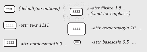
In the Hirlatz cave we use this symbol to tell the name of the adjacent (preview) maps. It is quite customizable and especially shows a way how to do label boxes. By default it prints the current surveys name in a white-filled box with rounded corners. You can adjust it per symbol by giving “-attr <var> <val>” options at the symbol in xtherion; see the code header for the available options.
From Benedikt Hallinger for Therion 6.0.3
  # Symbol to denote assigned survey.
  #   Option "-attr text <string>" shows given text; otherwise current survey is shown.
  #   Option "-attr bordersmooth <num>" overrides edge smoothness (0 for sharp edges)
  #   Option "-attr bordermargin <num>" overrides margin text/border
  #   Option "-attr basescale <num>" overrides basic text sizing factor (default text size)
  #   Option "-attr fillsize <s_pct>" fills with page background color; s_pct is percent of bbox size
  def p_u_mappe(expr pos, theta, sc, al) =
    T:=identity aligned al rotated theta scaled sc shifted pos;
    begingroup;
      % Basic config
      bordersmooth:=4;         % smoothness of box corners  (0=90° edges)
      bordermargin:=5.0bp;     % padding border->text
      basescale:=1.0;          % basic scaling of default-sized text
      fillsize:=-1.0;           % proportional size of label filling (percent)
      if known(ATTR_bordersmooth): bordersmooth:=scantokens(ATTR_bordersmooth); fi;
      if known(ATTR_bordermargin): bordermargin:=scantokens(ATTR_bordermargin); fi;
      if known(ATTR_basescale):    basescale:=scantokens(ATTR_basescale);       fi;
      if known(ATTR_fillsize):     fillsize:=scantokens(ATTR_fillsize);         fi;

      % GET LABEL TEXT:
      string txt;
      if known(ATTR_text):
          txt := ATTR_text;
      else:
              txt := ATTR__survey;
      fi;


      % PREPARE LABEL:
      lab:=thelabel(txt, (0.0,0.0));
      pickup PenA;                       % border thickness
      interim bboxmargin:=bordermargin;  % padding border->text

      % PREPARE BOX and DRAW BOX BACKGROUND:
      % q is the box as drawed, but we fill the place first before drawing
      q:=((bbox lab) smoothed bordersmooth) aligned al scaled (sc * basescale) rotated theta shifted pos;
      if (fillsize <> -1.0):
          % draw extending filled box around symbol
          if known(MapBackground):
              % from therion versions newer than 6.0.3+3551531+dev (23.11.2021) we use page background
              thfill ((bbox lab) smoothed bordersmooth) scaled (sc * basescale * fillsize) withcolor MapBackground;
          else:
              thfill ((bbox lab) smoothed bordersmooth) scaled (sc * basescale * fillsize) withcolor label_fill_color;
          fi;
      fi;
      % the following will draw the actual visible interiour-filling of the box
      thfill ((bbox lab) smoothed bordersmooth) scaled (sc * basescale) withcolor label_fill_color;

      % DRAW BOX
      draw q;

      % DRAW LABEL TEXT
      lab:=lab aligned al;
      lab:=lab scaled (sc * basescale);
      lab:=lab rotated theta;
      lab:=lab shifted pos;
      process_label(pos, 0.001);   % for some weird reason "0.0" does not work here and puts the label to map-center at scrap-rotation.
    endgroup;
  enddef;
Line Symbols
View whole centerline for underground
Stacho Mudrak
If you wish to view whole centerline for underground, just redefine symbol in layout:
    code mpost
      let l_survey_cave = l_survey_surface_SKBB;
    endcode
—-
Green colored continuous centerline
from Thomas Holder for version 5.2.x…
distributed under the GNU General Public License.
  def l_survey_cave (expr p) =
    pickup PenC;
    draw p withcolor 0.5green;
  enddef;
Make unsurveyed wall lines light-weight and dashed
A sample of how it looks is in the 'line rope' example below.
  code metapost
  %Bruce Mutton 2010.06.20 for Therion 5.3.9
  def l_wall_unsurveyed (expr P) =
    T:=identity;
    pickup PenC;
    thdraw P dashed evenly scaled (2*optical_zoom);
  enddef;
  endcode
—-
Visualize cave centreline shot flags with colour for splay and duplicate, and dash for approximate shot flags
For version 5.3.12+ Dec2013 (Bruce Mutton)
code metapost #thin grey cave splays, yellow duplicates and dashed approximate legs
  def l_survey_cave (expr P) =
  % always draws full centreline, rather than short stubs like default cave centrelines
	T:=identity;
	pickup PenC;
	if ATTR__shotflag_splay:
	  drawoptions(withcolor(0.5,0.5,0.5) withpen PenD);
	  thdraw P; %  grey & thin
        drawoptions();
	else: % not splay but may have either or both duplicate and approx flags set
		if ATTR__shotflag_duplicate:
		  drawoptions(withcolor (1,1,0)); % differentiate duplicate with colour yellow
		fi;

	    if ATTR__shotflag_approx:
		  thdraw P dashed evenly scaled optical_zoom;	% differentiate approx with dashed
		else:
		  thdraw P;
		fi;
	    thdrawoptions();
    fi;
  enddef;
  endcode
I was trying to get the duplicate and approximate symbols to appear in the legend as below, but so far it does not work…
initsymbol("l_survey_cave_duplicate");  %not working

def l_survey_cave_duplicate_legend =
  l_survey_cave_duplicate(((.2,.2) -- (.8,.8)); inscale) %not working
enddef;
—-
Define NZSS line wall presumed
Draws dashes with v shaped tick marks outside the passage like we tend to do in New Zealand…
A sample of how it looks is in the 'line rope' example below.
  code metapost
  %Bruce Mutton 2010.06.20 uses general code and adjust_step defined in therion source code by Martin Budaj
  %for Therion 5.3.8
  def l_wall_presumed (expr P) =
    T:=identity;
    cas := 0;                                 % cursor to step along path
    dlzka := arclength P;
    mojkrok:=adjust_step(dlzka, 1.5u);        % symbol length nudged to be multiple of path length
    q  := (-0.2u,-0.4u)--(0,0)--(0.2u,-0.4u); % define v shape
    forever:
      t1 := arctime (cas + mojkrok*1/5) of P;
      t  := arctime (cas + mojkrok/2) of P;
      t2 := arctime (cas + mojkrok*4/5) of P;
        pickup PenA;                          % thick
  	thdraw (subpath (t1,t2) of P);          % dash
  	  pickup PenC;                          % thin
      thdraw q rotated angle(thdir(P,t)) shifted (point t of P ); % v shape

      cas := cas + mojkrok;
      exitif cas > dlzka - (2*mojkrok/3);     % for rounding errors
    endfor;
  enddef;
  endcode
Define NZSS line chimney (aven)
  code metapost
  %Bruce Mutton 2012.06.10 uses general code for l_pit_UIS defined in therion source code by Martin Budaj 5.3.9
  % dots on righthand (rock) side of line spaced 0.2u, 0.2u same as floor-step ticks
  def l_chimney (expr P) =
    T:=identity;
    cas := 0;                            % cursor to step along path
    dlzka := arclength P;
    mojkrok:=adjust_step(dlzka, 0.25u);  % symbol length nudged to be multiple of path length
    q:= (0.20u,-0.20u) -- (0.21u,-0.21u);         % dot

    pickup PenC;  %2nd thinnest pen
    forever:
      t := arctime cas of P;
  	thdraw q rotated angle(thdir(P,t)) shifted (point t of P ); % draw dots
  	cas := cas + mojkrok;
      exitif cas > dlzka + (mojkrok / 3); % for rounding errors
    endfor;
    pickup PenB;   %2nd thickest pen
    thdraw P;      %continuous line
  enddef;
  endcode
Define NZSS line ceiling-step
This is just Therions default SKBB ceiling step, reflected so that it matches the UIS convention with the tick marks pointing away from the void space.
code metapost
%Bruce Mutton 2012.06.16 uses general code for l_ceilingstep_SKBB defined in therion source code by Martin Budaj 5.3.9
% but ticks on righthand (rock) side of line
def l_ceilingstep (expr P) =
  T:=identity;
  cas := 0;                            % cursor to step along path
  dlzka := arclength P;
  mojkrok:=adjust_step(dlzka, 0.8u);   % symbol length nudged to be multiple of path length
  pickup PenC;
  forever:
    t1 := arctime (cas + mojkrok*1/5) of P;
    t  := arctime (cas + mojkrok/2) of P;
    t2 := arctime (cas + mojkrok*4/5) of P;
    thdraw (subpath (t1,t2) of P);
    mark_ (P,t,-0.2u);                  % change sign to -0.2u
    cas := cas + mojkrok;
    exitif cas > dlzka - (2*mojkrok/3); % for rounding errors
  endfor;
enddef;
endcode
Define NZSS line ceiling-meander
This is just Therions default SKBB ceiling meander, with the symbols reflected so that it matches the UIS convention with the tick marks pointing away from the void space.
code metapost
%Bruce Mutton 2012.06.16 uses general code for l_ceilingmeander_SKBB defined in therion source code by Martin Budaj 5.3.9
% but ticks on outside (rock) side of lines
def l_ceilingmeander (expr P) =
  pair Pp;
  pair Pd;
  pair Pv;
  T:=identity;
  cas := 0;                           % cursor to step along path
  dlzka := arclength P;
  mojkrok:=adjust_step(dlzka, 0.8u);  % symbol length nudged to be multiple of path length
  pickup PenC;
  forever:
    t  := arctime (cas + mojkrok/2) of P;
    Pp := (point t of P);
    Pd := unitvector(thdir(P,t));
    Pv := Pd rotated 90;
    thdraw (Pp + 0.2u * Pv) --
          (Pp + 0.3u * Pv);              % add 0.1u to each moves ticks outside
    thdraw (Pp + 0.2u * Pv + 0.2u * Pd) --
          (Pp + 0.2u * Pv - 0.2u * Pd);
    thdraw (Pp - 0.2u * Pv) --
          (Pp - 0.3u * Pv);              % subtract 0.1u to each moves ticks outside
    thdraw (Pp - 0.2u * Pv + 0.2u * Pd) --
          (Pp - 0.2u * Pv - 0.2u * Pd);
    cas := cas + mojkrok;
    exitif cas > dlzka - (2*mojkrok/3);  % for rounding errors
  endfor;
enddef;
endcode
Draw a plank walk and (rope) handrail

  def l_u_plankwalk  (expr P) = T:=identity;
    cas := 0;
    dlzka := arclength P;
    mojrok := adjust_step(dlzka, 0.5u);
    pickup PenD;
    forever:
      t := arctime cas of P;
      thdraw ((point t of P) + 0.5 * u * unitvector(thdir(P,t) rotated 90)) --
      ((point t of P) - 0.5 * u * unitvector(thdir(P,t) rotated 90) );
      cas := cas + mojrok;
      exitif cas > dlzka + (mojrok/3);  % for rounding errors
    endfor;
    pickup PenC;
    %thdraw P;
    %draw path withcolor (0.5, 0 ,0)
   enddef;
   def l_u_handrail (expr P) = T:=identity;
    pair zz[];
    for t = 0 upto length P - 1:
      zz1 := point t of P;
      zz2 := point t+1 of P;
      zz3 := 0.5[zz1,zz2];
      zz4 := 0.25[zz1,zz2];
      zz5 := 0.75[zz1,zz2];
      pickup PenA;
      thdraw zz1 -- zz2 withcolor(.67,.41,.28); %planks
      thdraw zz1 shifted (0,1.6u) .. zz4 shifted (0,1.2u) .. zz3 shifted (0,1.6u) .. zz5 shifted (0,1.3u) .. zz2 shifted (0,1.6u) withcolor(.67,.41,.28);
      pickup pencircle scaled 1pt;
      thdraw zz1 shifted (0,-1.2u) -- zz1 shifted (0,2u) withcolor(.67,.41,.28); %first post
      thdraw zz3 -- zz3 shifted (0,2u) withcolor(.67,.41,.28); %mid post
    endfor;
    thdraw zz2 shifted (0,-6u) -- zz2 shifted (0,2u) withcolor(.67,.41,.30); %last post
   enddef;
Define a doline

  def l_u_doline (expr P) =
    T:=identity;
    laenge:= arclength P;
    symsize:=adjust_step(laenge,2u);
    triangle_width:=symsize/10;
    cur:=(symsize-triangle_width)/2;
    pickup PenC;
    forever:
      t1 := arctime (cur) of P;
      t  := arctime (cur + triangle_width/2) of P;
      t2 := arctime (cur + triangle_width) of P;
        thfill (subpath (t1,t2) of P) --
          ((point t of P) + symsize/2 * unitvector(thdir(P,t) rotated 90)) --
          cycle;
        thdraw (point t2 of P) --((point t of P) + symsize/2 * unitvector(thdir(P,t) rotated 90)) --
          (point t1 of P) withcolor (0.5, 0, 0);
      cur := cur + symsize;
      exitif cur > laenge - (1*symsize/3); % for rounding errors
      t1:=arctime (cur) of P;
    endfor;
  enddef;
Define Line Handrail
Andrew Atkinson

def l_u_rail (expr P) =
T:=identity;
cas := 0;
dlzka := arclength P;
mojkrok:=adjust_step(dlzka, 0.8u);
pickup PenC;
forever:
  t0 := arctime (cas) of P;
  t1 := arctime (cas + mojkrok*2/5) of P;
  t  := arctime (cas + mojkrok/2) of P;
  t4 := arctime (cas + mojkrok*3/5) of P;
  t5 := arctime (cas + mojkrok) of P;
  thdraw (subpath (t0,t1) of P);
  thdraw (subpath (t4,t5) of P);
  drawdot
     (point t of P);
  #mark_ (P,t,0.02u);
  #mark_ (P,t,-0.02u);
   #f := (P,t,0.2u);
   #draw f;
  cas := cas + mojkrok;
  exitif cas > dlzka - (2*mojkrok/3); % for rounding errors
endfor;
enddef;
initsymbol("l_u_rail")
Strata
Line symbol for strata for cross sections. It works exactly as line section symbol but you should use -clip off option:
    def l_u_strata (expr P) =
      T:=identity;
      path Q; Q = punked P;
      for t = 0 upto length P - 1:
        pair zz[];
        zz1 := point t of P;
        zz2 := point t+1 of P;
        zz3 := postcontrol t of P;
        zz4 := precontrol t+1 of P;
        linecap_prev:=linecap;
        linecap:=0;
        if (length(zz3-1/3[zz1,zz2]) > 0.1pt) or
           (length(zz4-2/3[zz1,zz2]) > 0.1pt):
          zz5 = whatever[zz1,zz2];
          (zz3-zz5) = whatever * (zz1-zz2) rotated 90;
          pickup pencircle scaled 1 mm;
          draw zz1--zz5 dashed evenly;
          pickup PenA;
          draw zz1--zz5 withcolor background;
          zz6 = whatever[zz1,zz2];
          (zz4-zz6) = whatever * (zz1-zz2) rotated 90;
          pickup pencircle scaled 1 mm;
          draw zz2--zz6 dashed evenly;
          pickup PenA;
          draw zz2--zz6 withcolor background;
        else:
          pickup pencircle scaled 1 mm;
          draw zz1--zz2 dashed evenly;
          pickup PenA;
          draw zz1--zz2 withcolor background;
        fi;
        linecap:=linecap_prev;   % to prevent problems with dots of other symbols
      endfor;
    enddef;

Fault
Line symbol for fault. It works exactly as line section symbol but you should use -clip off option:
    def l_u_fault (expr P) =
      T:=identity;
      path Q; Q = punked P;
      pickup PenA;
      for t = 0 upto length P - 1:
        pair zz[];
        zz1 := point t of P;
        zz2 := point t+1 of P;
        zz3 := postcontrol t of P;
        zz4 := precontrol t+1 of P;
        if (length(zz3-1/3[zz1,zz2]) > 0.1pt) or
           (length(zz4-2/3[zz1,zz2]) > 0.1pt):
          zz5 = whatever[zz1,zz2];
          (zz3-zz5) = whatever * (zz1-zz2) rotated 90;
          draw zz1--zz5 dashed evenly;
          zz6 = whatever[zz1,zz2];
          (zz4-zz6) = whatever * (zz1-zz2) rotated 90;
          draw zz2--zz6 dashed evenly;
        else:
          draw zz1--zz2 dashed evenly;
        fi;
      endfor;
    enddef;

Pit lines that look different in elevation view
Pits use the same appearance in both plan and elevation views. However, it may be desirable for a pit edge to be drawn as a pitch in plan view, but a ledge in elevation view. This is common with Rigging topos, for example, where the plan uses a pit symbol, but the same same drop in the elevation view will normally be shown with a different symbol, such as a dashed line, to indicate that a traverse may be required along a ledge. It is still a pitch, so it should use the same semantic “l_pit” symbol, even though the rendering should be different. This example shows how to show a pit symbol in plan view, but replace it with a dashed ledge line (borrowed from a temporary border) in elevation view:
code metapost
  def l_pit_MY (expr P)=
    if ATTR__elevation:
      l_border_temporary_SKBB(P);
    else:
      l_pit_UIS(P);
    fi;
  enddef;
  initsymbol("l_pit_MY");
endcode
Use it with this line in your layout:
symbol-assign line pit MY
Simplified rope lines
The default Therion rope symbol is very pretty, doing fancy rebelays and anchors. This works well for simple cases, but when trying to draw Rigging topos, it tries to add anchors and rebelays in places where you were just trying to draw Y-hang knots, and it sometimes fails to draw lines because it decides that they were too short.
It is possible to disable the anchors and rebelays by adding two options to a linepoint (not the line itself), and hoping that you never accidentally remove that particular linepoint. These options apply to the whole line rather than an individual linepoint, so you cannot fine control the use of rebelays and linepoints. It is best to just disable them, use the usual Bézier curve controls, and manually add anchors.
This can become annoying while editing lines since you may delete the linepoint where you set the options, so you may just want to redefine rope lines to use your own symbol, which does not try to be clever. Unfortunately, Therion does not let you define a custom symbol for ropes (like l_rope_MY) - they are special. So instead, you must overwrite the l_rope macro directly:
code metapost

  % store the original clean_legend_box
  boolean l_rope_MY_inlegend;
  l_rope_MY_inlegend:=false;
  let l_rope_MY_legend_box = clean_legend_box;
  % redefine clean_legend_box to store the flag, then run the original
  def clean_legend_box =
    l_rope_MY_inlegend:=true;
    l_rope_MY_legend_box;
  enddef;

  def l_rope(expr P, show_anchors, show_rebelays)=
    T:=identity;
    pickup PenB;
    if l_rope_MY_inlegend:
      % drawing the legend - this gets run twice, since Therion draws two ropes, one for each parameter
      if show_rebelays:
        thdraw ((.35,.9) -- (.4,.85) -- (.4,.5) .. controls (.4,.4) and (.45,.4) .. (.5,.5) -- (.55,.45) -- (.55,.1)) inscale;
        thdraw ((.4,.85) -- (.45,.9)) inscale;
        thdraw ((.55,.45) -- (.6,.5)) inscale;
        thfill fullcircle scaled .15u shifted ((.35,.9) inscale);
        thfill fullcircle scaled .15u shifted ((.45,.9) inscale);
        thfill fullcircle scaled .15u shifted ((.5,.5) inscale);
        thfill fullcircle scaled .15u shifted ((.6,.5) inscale);
      fi;
    else:
      begingroup;
        save type;
        string type;
        if known ATTR_type:
          type:=ATTR_type;
        else:
          type:="primary";
        fi;
        if type = "secondary":
          thdraw P withcolor (0.7, 0.7, 0.7);
        else:
          thdraw P;
        fi;
      endgroup;
    fi;
  enddef;
endcode
Rope lines default to using the standard colour (black, unless you change it with “symbol-color”). Optionally use it with the following -attr setting “value” options on the line:
- -attr type primary = (default) use the default colour (black)
- -attr type secondary = draws in grey
This allows you to have ropes with two different colours, useful if ropes are optional or follow an uncommon optional route.
Deviations
For Rigging topos, one of the most easily recognised symbols used in the UK is a rope reaching from a wall towards the main rope, with a small oval around it, pulling the rope to the side. This symbol shows an example of cutoffafter, used to allow the deviation's rope to share a linepoint with the main rope, but without showing the deviation rope inside the oval (a reverse clipping effect in MetaPost!).
code metapost
  def l_u_deviation (expr P) =
    begingroup;
      save ellipse;
      T:=identity;
      pickup PenC;
      path ellipse;
      ellipse:=fullcircle xscaled (.5u) yscaled (.25u) shifted (point (length P) of P);
      thdraw P cutafter ellipse;
      draw ellipse;
    endgroup;
  enddef;
  initsymbol("l_u_deviation");
  def l_u_deviation_legend =
    l_u_deviation(((.1,.5)--(.8,.5)) inscale);
  enddef;
endcode

Select this as line type “u” with “-subtype deviation” in its options. Use it with this line in your layout:
text en "line u:deviation" "deviation"
Shuttering, two parallel lines
This symbol is designed for use in mine surveys, where passages may have the ceiling or walls made up from wooden boards holding back debris (deads). Often these boards are a series of flat boards then stronger timbers, which is what the dashed line is supposed to represent.
This symbol is an example of how to draw two parallel lines when given only a single path to work from. It could be done simply by sampling down the length of the path, and adding a new path with a point rotated a chosen distance perpendicular to the original path's direction. However, that will fail to follow sharper corners in the original path properly, and will instead create a weird loop. To avoid this, a separate semi-circular path is created slightly to the side at each sample point, and if it intersects the original path, a corner is nearby, and the sample point is not added to the new path - the points that do not create intersections are used instead. This technique is inspired heavily by the approach used by Therion's own symbols, but simplified since it only needs to create parallel lines (rather than more complex tines or arrows).
code metapost
  def l_u_shuttering (expr P)=
    begingroup;
      save pathlength, athick, cthick, linegap, testdiameter, testpath, innerpath, newpoint, curlength, intersections, samplepoint, accuracy, dashes, chosenpattern;
      T:=identity;
      % main wall line
      thdraw P withpen PenA;
      % work out a parallel path
      % the easy way is to sample direction every few units, and add a parallel point into a new path
      % however, this causes weird loops at sharp corners, so check if a sharp corner is coming up within
      % the length of the gap between lines, and ignore that point if so
      pathlength:=arclength P;
      % gap between the main line and dashed line
      if known ATTR_linegap:
        linegap:=scantokens(ATTR_linegap) * u;
      else:
        linegap:=0.125u;
      fi;
      % how tightly should the dashed line follow curves and corners - higher numbers take more time to process
      if known ATTR_accuracy:
        accuracy:=scantokens(ATTR_accuracy);
      else:
        accuracy:=4;
      fi;
      athick:=(xpart (lrcorner PenA)) - (xpart (llcorner PenA));
      cthick:=(xpart (lrcorner PenC)) - (xpart (llcorner PenC));
      testdiameter:=athick + cthick + 2*linegap;
      path testpath;
      testpath:=halfcircle scaled testdiameter shifted (0,athick/2);
      pair newpoint;
      path innerpath;
      pair intersections;
      curlength:=0;
      forever:
        samplepoint:=arctime curlength of P;
        % every now and then along the line, place a semicircle, rotated to face away from the line, offset by the thickness of the line,
        % with a radius the same as the gap between the lines - if its ends touch the main line's centre, the corner is too sharp to use
        % this point
        intersections:=P intersectiontimes (testpath rotated (angle thdir(P,samplepoint)) shifted (point samplepoint of P));
        % if there are no intersections, intersectiontimes returns (-1,-1), otherwise it returns the distance along each path (P,testpath)
        % where the intersection happened >=0
        % enable for debugging
        %if (xpart intersections) = -1:
        %  thdraw testpath rotated (angle thdir(P,samplepoint)) shifted (point samplepoint of P) withpen (pencircle scaled 0.01u) withcolor .7;
        %else:
        %  thdraw testpath rotated (angle thdir(P,samplepoint)) shifted (point samplepoint of P) withpen (pencircle scaled 0.01u) withcolor (100*(xpart intersections)/(arclength P),100*(ypart intersections)/(arclength testpath),0);
        %fi;
        if (xpart intersections) = -1:
          newpoint:=((point samplepoint of P) shifted (linegap * unitvector(thdir(P,samplepoint) rotated 90)));
          % enable for debugging
          %thdraw newpoint withcolor (0,0,100) withpen PenC;
          if known innerpath:
            innerpath:=innerpath .. newpoint{thdir(P,samplepoint)};
          else:
            innerpath:=newpoint{thdir(P,samplepoint)};
          fi;
        fi;
        exitif curlength = pathlength;
        % move in small steps, to take account of tight backwards curves, and to get points near a corner
        curlength:=curlength + testdiameter/accuracy;
        if curlength > pathlength:
          curlength:=pathlength;
        fi;
      endfor;
      if known innerpath:
        if cycle P:
          innerpath:=innerpath .. cycle;
        fi;
        string dashes;
        if known ATTR_dashes:
          dashes:=ATTR_dashes;
        else:
          dashes:="dashdotdot";
        fi;
        picture chosenpattern;
        if dashes = "dashed":
          chosenpattern:=evenly;
        elseif dashes = "dotted":
          chosenpattern:=withdots;
        elseif dashes = "dashdot":
          chosenpattern:=dashpattern(on 3*cthick off 3*cthick on 0 off 3*cthick);
        elseif dashes = "dashdashdotdot":
          chosenpattern:=dashpattern(on 3*cthick off 3*cthick on 3*cthick off 3*cthick on 0 off 3*cthick on 0 off 3*cthick);
        else:
          chosenpattern:=dashpattern(on 3*cthick off 3*cthick on 0 off 3*cthick on 0 off 3*cthick);
        fi;
        thdraw innerpath dashed chosenpattern withpen PenC;
      fi;
    endgroup;
  enddef;
  initsymbol("l_u_shuttering");
endcode

Select this as line type “u” with “-subtype shuttering” in its options. Use it with this line in your layout:
text en "line u:shuttering" "shuttering"
Each line will need the “-outline out” option specified to make it a cave wall. Optionally use it with the following -attr setting “value” options on the line:
- -attr linegap 0.125 = the gap between the outer wall and inner dashed line - too big and the inner line will curve significantly at corners
- -attr accuracy 4 = how tightly should the dashed line follow curves and corners - higher numbers take more time to process
- -attr dashes dashdotdot = (default) the style of the dashed line
- -attr dashes dashdashdotdot = exactly what it says
- -attr dashes dashdot = (note; this can be confused with line wall overlying)
- -attr dashes dotted = (note; this can be confused with line chimney NZSS)
- -attr dashes dashed = (note; this can be confused with line wall underlying or presumed UIS)
Trees
Trees are often found in the entrances to caves, and sometimes a survey deserves to show the trees. This is particularly common with Rigging topos for surface shafts, where a tree may be used as a rope belay, but it also may be in particularly large entrances which contain forests. A tree may be created as a single point symbol, but this then makes it difficult to scale the heights and widths perfectly, and even harder to attach other lines (like ropes or tethers) to the sides of them. It also means that when trying to draw a particularly distinctive tree which must be used as a belay, it is not possible to show it in a recognisable way.
This is therefore a pair of symbols. The first is for the sides of the tree trunk (which could also be used to create jagged shapes for conifers), and the second is for the bushy leaves at the top of a deciduous tree. The sides of the tree can therefore be curved or branched as needed, with linepoints added for attaching rope lines, the surface lines, and the bushy part of the tree to. For plans, the bushy part alone would normally work, as a closed, circular line.
The trunk/branches (or conifer edges):
code metapost
  def l_u_treetrunk(expr P)=
    T:=identity;
    pickup PenC;
    draw P;
  enddef;
  initsymbol("l_u_treetrunk");
  def l_u_treetrunk_legend =
    l_u_treetrunk(((.4,.9) .. controls (.5,.8) and (.44,.2) .. (.3,0)) inscale);
    l_u_treetrunk(((.6,0) .. controls (.55,.2) and (.5,.7) .. (.7,.9)) inscale);
    l_u_treetrunk(((.65,.95) .. controls (.6,.8) and (.5,.7) .. (.45,.95)) inscale);
  enddef;
endcode
The bushy part, which is automatically bulged out:
code metapost
  def l_u_bush (expr P)=
    begingroup;
      save pathlength, bulges, bulgesper, bulgesize, newpoint, newdirection, bulgedpath, steps, pathfactor, slopefactor, extradirection, curincrement, samplepoint, sinefactor;
      T:=identity;
      pathlength:=arclength P;
      if known ATTR_bulges:
        bulges:=max(ceiling(scantokens(ATTR_bulges)),1);
      else:
        bulges:=10;
      fi;
      if known ATTR_bulgesper:
        if ATTR_bulgesper = "tenu":
          bulges:=ceiling(bulges*(pathlength/10u));
        fi;
      fi;
      if known ATTR_bulgesize:
        bulgesize:=scantokens(ATTR_bulgesize) * u;
      else:
        bulgesize:=u;
      fi;
      pair newpoint;
      pair newdirection;
      path bulgedpath;
      steps:=3; % number of samples per bulge
      % precompute various numbers to avoid arithmetic overflows with large numbers of bulges
      pathfactor:=pathlength/(steps*bulges);
      slopefactor:=pathlength/(bulges*3.14159);
      extradirection:=angle(slopefactor,-bulgesize*cosd(180));
      curincrement:=0;
      forever:
        samplepoint:=arctime (curincrement*pathfactor) of P;
        sinefactor:=180 * (curincrement mod steps) / steps;
        newpoint:=((point samplepoint of P) shifted (bulgesize * sind(sinefactor) * unitvector(thdir(P,samplepoint) rotated -90)));
        newdirection:=thdir(P,samplepoint) rotated angle(slopefactor,-bulgesize*cosd(sinefactor));
        % enable for debugging
        %thdraw (point samplepoint of P) withcolor (100,0,0) withpen PenC;
        %thdraw newpoint--(newpoint shifted (bulgesize*unitvector(newdirection))) withcolor (0,0,100) withpen PenC;
        if known bulgedpath:
          if ((curincrement mod steps) = 0):
            % this is a corner where one bulge ends and another starts, two points are needed so that the direction vectors can control curves
            %thdraw newpoint--(newpoint shifted (bulgesize*unitvector(thdir(P,samplepoint) rotated extradirection))) withcolor (0,0,100) withpen PenC;
            bulgedpath:=bulgedpath .. newpoint{thdir(P,samplepoint) rotated extradirection};
            if curincrement <> steps * bulges:
              % don't add one in the final increment, since --cycle then has two identical point vectors
              bulgedpath:=bulgedpath -- newpoint{newdirection};
            fi;
          else:
            bulgedpath:=bulgedpath .. newpoint{newdirection};
          fi;
        else:
          % first point in the path
          bulgedpath:=newpoint{newdirection};
        fi;
        exitif curincrement = steps * bulges;
        curincrement:=curincrement + 1;
      endfor;
      if cycle P:
        bulgedpath:=bulgedpath -- cycle;
      fi;
      thdraw bulgedpath withpen PenC;
    endgroup;
  enddef;
  initsymbol("l_u_bush");
  def l_u_bush_legend =
    begingroup;
      save ATTR_bulgesize;
      string ATTR_bulgesize;
      ATTR_bulgesize:=".2";
      l_u_bush(((.6,.1)..controls (.8,.3) and (.9,.7)..(.5,.9)..controls (.1,.7) and (.2,.3)..(.4,.1)) inscale);
    endgroup;
  enddef;
endcode

Select these as line type “u” with “-subtype treetrunk” and “-subtype bush” in their options. Remember to set “-clip off” on the lines if they are going to be used outside of the cave walls. Use it with these lines in your layout:
text en "line u:treetrunk" "tree"
text en "line u:bush" "bush"
Use as many treetrunk and bush lines as needed to make the perfect tree for your tastes. The bush lines have several “-attr setting value” options which can be used to control just how bulgy they are.
- -attr bulges 10 = the number of bulges
- -attr bulgesper line = (default) the number of bulges should be spread over the whole line
- -attr bulgesper tenu = the number of bulges should be used per approx 10u of the line's length (so the bulge length remains fairly constant, and longer lines get more bulges
- -attr bulgesize 1 = how much each bulge extends away from the line, in number of “u” units
Shoring
Metal bars and wooden beams are a common part of chokes, and are not normally drawn on a survey (though sometimes that are drawn, for particularly special cases). However, sometimes they are also used for rigging, and that is where they become important. Therion does not do anything with the “-scale” option on lines (it is silently ignored), but sometimes it is needed for a line symbol, and this is one of those cases - some shoring deserves a thick line, some does not. This symbol is therefore an example of how to provide an equivalent “-attr scale xs” option which can be used in the symbol code. The values it supports are the same as a regular -scale option (xs, s, m, l, xl).
code metapost
  def l_u_shoring (expr P)=
    begingroup;
      save scale;
      T:=identity;
      string scale;
      if known ATTR_scale:
        scale:=ATTR_scale;
      else:
        scale:="m";
      fi;
      if scale = "xs": pickup PenD scaled 0.5;
      elseif scale = "s": pickup PenD;
      elseif scale = "m": pickup PenC;
      elseif scale = "l": pickup PenB;
      elseif scale = "xl": pickup PenA;
      fi;
      thdraw P;
    endgroup;
  enddef;
  initsymbol("l_u_shoring");
  def l_u_shoring_legend =
    l_u_shoring(((.1,.1)--(.95,.8)) inscale);
    l_u_shoring(((.9,.9)--(.05,.2)) inscale);
  enddef;
endcode

Select this as line type “u” with “-subtype shoring” in its options. Use it with this line in your layout:
text en "line u:shoring" "shoring/bars"
Centreline that is only visible when not in a scrap
Sometimes, you might want to show a centreline for a section of the cave where you do not have any wall data, if you are using a map made up from surveys and other maps. However, you might not want to show the walls within your regular scraps where you have wall data, since they are distracting and meaningless for viewers. There is no setting for this, since “symbol-hide group centreline” affects all centrelines at once, so it must be done through MetaPost:
code metapost
  def l_survey_cave_MY(expr P) =
    if ATTR__scrap_centerline:
      l_survey_cave_SKBB(P);
    fi;
  enddef;
  initsymbol("l_survey_cave_MY");
endcode
You may notice the misleadingly named “ATTR__scrap_centerline”, which does not mean “centreline within a scrap”. Instead, it means “a virtual scrap automatically created, made up entirely of centreline”, which is what Therion creates when you ask it to include survey data within a map.
Use it with this line in your layout:
symbol-assign line survey:cave MY
You can use a similar approach for l_survey_surface_MY (surface survey legs), p_station_temporary_MY, p_station_natural_MY, p_station_painted_MY and p_station_fixed_MY (survey stations) if you needed to show those outside too.
Break line
When a section of are omitted or shortened, typically used with rigging topos, the common approach is to show a double line wherever the passage has been omitted. Usually, it is drawn at an angle of about 45 degrees. This can either be used on a single scrap with a double line over the passage to show that it is much longer than shown, or it is used to end the scrap, then a second double line is used to start the next scrap; this second version is normally used when the passage on either side of the break is of different dimensions.
This code is an example of how to extend a line beyond the defined ends, using additional points. It also shows how to cope with the fact that (as of the time of writing) Therion does not offer a variable that allows you to read the “map-bg” colour. It also shows how to cope with Therion trying to recognise keywords inside “code metapost” sections.
code metapost
  def l_u_break(expr P)=
    begingroup;
      save mainpath, parallel, orientation, direction, gapsize;
      T:=identity;
      gapsize:=u/3;
      path mainpath;
      %make the ends stick out beyond the passage
      mainpath:=( (point 0 of P) + u * unitvector( thdir(P, 0) rotated 180 ) / 2 )
                -- P --
                ( (point (length P) of P) + u * unitvector( thdir(P, arclength P) ) / 2 );
      path parallel;
      string orientation;
      orientation:=if known ATTR_orientation: ATTR_orientation; else: "horizontal"; fi;
      if orientation = "vertical":
        direction:=if (xpart (point 0 of mainpath)) > (xpart (point (length mainpath) of mainpath)): 1; else: -1; fi;
        parallel:=mainpath shifted (0, direction * gapsize);
      else:
        direction:=if (ypart (point 0 of mainpath)) > (ypart (point (length mainpath) of mainpath)): -1; else: 1; fi;
        parallel:=mainpath shifted (direction * gapsize, 0);
      fi;
      if known fill_l_u_break:
        thfill (mainpath -- (reverse parallel) -- cycle) withcolor fill_l_u_break;
      else:
        thunfill (mainpath -- (reverse parallel) -- cycle);
      fi;
      pickup PenC;
      thdraw mainpath;
      thdraw parallel;
    endgroup;
  enddef;
  initsymbol("l_u_break");
  def l_u_break_legend =
    l_wall_bedrock(((0,.2) .. controls (.3,.2) and (.4,.4) .. (.6,.4)) inscale);
    l_wall_bedrock(((.7,.6) .. controls (.4,.6) and (.3,.4) .. (0,.4)) inscale);
    l_u_break(((.6,.4) -- (.7,.6)) inscale);
  enddef;
endcode

Select this as line type “u” with “-subtype break” in its options. You will also need to define it with “-clip off” in its options to allow the ends of the line to show up outside the walls. Typically, you will also need to use “-place top” in its options to allow it to be placed over the top of any walls, so that it can blank out the wall in between the double lines (either that or you need to ensure that it appears before any wall lines in its scrap, but this can make maintenance harder).
Use it with this line in your layout:
text en "line u:break" "passage omitted/offset"
By default, it will pick up the colour of the scrap background, to put between the double lines. However, it normally looks better with the map-bg colour between them. Unfortunately, Therion does not appear to expose this colour to MetaPost code (it is created in raw Tex). So you will need to do it manually. If you do not specify map-bg, it is white; “(1, 1, 1)” in MetaPost. If you have set it to a colour like “70”, this is “(.7, .7, .7)” in MetaPost. If you have set it to a colour like “[70 35 50]”, this is “(.7, .35, .5)” in MetaPost. The code will check for a variable called fill_l_u_break, and will try to use it as a fill colour if it exists.
You cannot use “color fill_l_u_break;” in a “code metapost” section, because Therion will try to treat the keyword “color” as a Therion command instead of a MetaPost keyword. You can either write “;color fill_l_u_break;” with a leading semicolon which MetaPost will ignore, or use the synonym “rgbcolor fill_l_u_break;” which Metpost understands but Therion will not recognise.
code metapost
  rgbcolor fill_l_u_break;
  fill_l_u_break:=(1,1,1);
endcode
By default, the break line is set up for use along a horizontal passage. This follows the usual style used in the UK; two parallel lines, separated by a horizontal gap, with the tops and bottoms horizontally aligned (no matter whether the lines are drawn vertically or tilted at 45 degrees or more). If you are using it on a vertical section of cave, you can set the “-attr orientation vertical” option on the line. This will cause it to leave a vertical gap between the lines, and to align them horizontally compared with each other. This makes only a tiny difference when tilted at 45 degrees, but it looks better, and matches the normal style used in rigging topos.
Area Symbols
Show area water in a different color
Martin Budaj
Add in layout:
  code metapost
    def a_water (expr p) =
      T:=identity;
      thfill p withcolor (0.1, 0.2, 0.8);
    enddef;
  endcode
Colors are in order R, G, B — 0=0 1=255. Color (0.1, 0.2, 0.8) means (25 51 204) in Photoshop - quite dark blue. Light blue could be for example (123 213 255) in Photoshop - it is (123/255, 213/255, 255/255) or (0.48, 0.84 1.0) for Metapost.
See also this spreadsheet to visualise and convert between colour formats.
Modification MetaPost code for NSS (Philip Schuchardt)
This is how you overload metapost symbols:
######### thconfig file ###########
  input layout.th
  source main.th

  #One page map
  export map -layout plan -output ABC.pdf
  export map -layout print -output ABC_Printable.pdf
########## Heres my layout.th ################
  layout plan
    scale 1 200 #Working map scale
    #scale 1 400
    #scale 1 600 #1" to 50'
    #base-scale 1 600
    units imperial
    legend on
    color map-fg altitude
    transparency on
    debug station-names

    #PDF DOCUMENTION
    doc-author "Philip Schuchardt"
    code tex-map
      \cavename={Alva Blankenship Cave (WORKING COPY }
      \comment{Cartography By: Philip Schuchardt and Philip Balister  \copyright 2006 VPI Cave Club}
    endcode

  code metapost
      def l_wall_bedrock_AMER (expr P) =
        T:=identity;
        pickup PenA;
        thdraw P;
      enddef;

      def p_gradient_AMER (expr pos,theta,sc,al) =
          U:=(.15u, .4u);
          T:=identity aligned al rotated theta scaled sc shifted pos;
          pickup PenC;

          #Left Hand side
          thdraw (-.3u, -.2u) -- (-.7u, .1u);
          thdraw (-.2u, -.1u) -- (-.4u, .6u);

          #Centerline
          thdraw (0u, 0u) -- (0u, .9u);

          #Right side
          thdraw (.3u, -.2u) -- (.7u, .1u);
          thdraw (.2u, -.1u) -- (.4u, .6u);

      enddef;

      def a_sand_AMER (expr p) =
        T:=identity;
        %  thclean p;
        pickup PenC;
        path q; q = bbox p;
        picture tmp_pic;
        tmp_pic := image(
          for i = xpart llcorner q step .3u until xpart urcorner q:
            for j = ypart llcorner q step .3u until ypart urcorner q:
              draw origin shifted ((i,j) randomized 0.2u) withpen PenC;
            endfor;
          endfor;
        );
        clip tmp_pic to p;
        draw tmp_pic;
      enddef;

      def a_debris_AMER (expr p) =
      T:=identity;
      pickup PenC;
      path q, qq; q = bbox p;
      picture tmp_pic;
      tmp_pic := image(
        for i = xpart llcorner q step u until xpart urcorner q:
         for j = ypart llcorner q step u until ypart urcorner q:
            qq := punked
  (((-.2u,-.2u)--(.2u,-.2u)--(.2u,.2u)--(-.2u,.2u)--cycle)
  	     randomized (u/2))
               rotated uniformdeviate(360)
               shifted ((i,j) randomized u);
  	   if xpart (p intersectiontimes qq) < 0:
  	    thclean qq;
  	    thdraw qq;
  	   fi;
          endfor;
        endfor;
      );
      clip tmp_pic to p;
      draw tmp_pic;
    enddef;

    initsymbol ("a_sand_AMER");
    initsymbol ("a_debris_AMER");
    initsymbol ("p_gradient_AMER");
    initsymbol ("l_wall_bedrock_AMER");
    endcode

    symbol-assign area sand AMER
    symbol-assign area debris AMER
    symbol-assign line wall:bedrock AMER
    symbol-assign point gradient AMER

  endlayout
Modification of fill densities
Stacho Mudrák
   code metapost
   % pattern for water, .18u is density of lines.
   beginpattern(pattern_water_MY);
       draw origin--10up withpen pensquare scaled (0.02u);
       patternxstep(.18u);
       patterntransform(identity rotated 45);
   endpattern;

  % pattern for sump, 0.25u is density in this case.
  beginpattern(pattern_sump_MY);
       draw origin--(0,.25u) withpen pensquare scaled (0.02u);
       draw origin--(.25u,0) withpen pensquare scaled (0.02u);
       patterntransform(identity rotated 45);
  endpattern;

  def a_water (expr Path) =
     T:=identity;
     thclean Path;
     thfill Path withpattern pattern_water_MY;
  enddef;

  def a_sump (expr Path) =
     T:=identity;
     thclean Path;
     thfill Path withpattern pattern_sump_MY;
  enddef;

  endcode
… and modify 0.18u in water pattern (and/or 0.25u in sump pattern) to number you need.
In therion, area symbols are defined two ways:
- Using patterns - no randomness, very small PDF file size. You need to redefine pattern (begin|endpattern) and symbol macro (a_water).
- Using drawing/clipping into Path - random look, large PDF size. Here you need to redefine only symbol (a_water) macro.
Water is the case of pattern fills. Blocks and others are random.
For other area symbols, see mpost/thArea.mp file for metapost source codes.
POINT BLOCK +size adjust (symbolsize)
Stefan Oswald
  code metapost
   def p_blocks_UIS (expr pos,theta,sc,al)=
    symbolsize:=1.0u; %Factor*u; Factor=size of the blocks
    U:=(.5u,.5u);
    T:=identity aligned al rotated theta scaled sc shifted pos;
    pickup PenC;
    thdraw (.0symbolsize,.0symbolsize)--(1.0symbolsize,-.5symbolsize)--(0.0symbolsize,-1.5symbolsize)--(-1.0symbolsize,-1.0symbolsize)--cycle;
    thdraw (.5symbolsize,-.25symbolsize)--(1.0symbolsize,.5symbolsize)--(0.0symbolsize,1.5symbolsize)--(-0.5symbolsize,.5symbolsize);
    thdraw (.0symbolsize,.0symbolsize)--(.0symbolsize,.5symbolsize)--(-1.5symbolsize,.5symbolsize)--(-1.5symbolsize,-0.5symbolsize)--(-0.5symbolsize,-0.5symbolsize);
   enddef;
  endcode
AREA BLOCK + density adjust (distance)
Stefan Oswald
  code metapost
    def a_blocks (expr p) =
      distance:=1;
      T:=identity;
      pickup PenC;
      path q, qq; q = bbox p;
      picture tmp_pic;
      uu := max(u, (xpart urcorner q - xpart llcorner q)/100, (ypart urcorner q - ypart     llcorner q)/100);
      tmp_pic := image(
        for i = xpart llcorner q step distance*uu until xpart urcorner q:
          for j = ypart llcorner q step distance*uu until ypart urcorner q:
            qq := punked (((-.5uu,-.5uu)--(.5uu,-.5uu)--(.5uu,.5uu)--(-.5uu,.5uu)--cycle)
          randomized (uu/2))
                 rotated uniformdeviate(360)
                 shifted ((i,j) randomized 1.0uu);
      if xpart (p intersectiontimes qq) < 0:
        thclean qq;
        thdraw qq;
      fi;
          endfor;
        endfor;
      );
      clip tmp_pic to p;
      draw tmp_pic;
    enddef;
  endcode
Make area AUT sand more spaced out and more random
A sample of how it looks is in the 'area point colour water' example below.
  code metapost
  %Bruce Mutton 2010.06.20, after original author Georg Pacher
  %for Therion 5.3.8
  beginpattern(pattern_sand);
      pickup PenC;
      p:= origin -- (0.01u,0.01u);
      for i=0.0u step 0.4u until 2.4u:  %AUT is step 0.2u
          for j=0.0u step 0.4u until 2.4u:  %AUT is step 0.2u
            draw p rotated uniformdeviate(360)
             shifted ((i,j) randomized 0.4u);  %%AUT is 0.09u
          endfor;
      endfor;
      if BaseScale<=2.5:
        my_step:=2.6u;  %mystep controls tessilation pattern, must synchronise with i, j above, was 2.4u
      else:
        my_step:=2.8u;  %was 2.6u
      fi;
      patternstep(my_step,my_step);
  endpattern;
  def a_sand (expr Path) =
    T:=identity;
    %thclean Path; %makes passage colour more intense under area, not good for sand
    thfill Path withpattern pattern_sand ;
  enddef;
  endcode
Area blocks with colored rock-borders only (not filled)
Martin Budaj
symbol-colour area blocks [67 31 4]
   code metapost
   def a_blocks (expr p) =
     T:=identity;
     pickup PenC;
     path q, qq; q = bbox p;
     picture tmp_pic;
     uu := max(u, (xpart urcorner q - xpart llcorner q)/100, (ypart urcorner q - ypart llcorner q)/100);
     tmp_pic := image(
       for i = xpart llcorner q step 2uu until xpart urcorner q:
         for j = ypart llcorner q step 2uu until ypart urcorner q:
           qq := punked (((-.5uu,-.5uu)--(.5uu,-.5uu)--(.5uu,.5uu)--(-.5uu,.5uu)--cycle)
          randomized (uu/2))
                rotated uniformdeviate(360)
                shifted ((i,j) randomized 1.6uu);
           if xpart (p intersectiontimes qq) < 0:
                thdraw qq;
           fi;
         endfor;
       endfor;
     );
     clip tmp_pic to p;
     draw tmp_pic;
   enddef;
This is modified a_blocks_SKBB definition with “thclean qq;” statement removed. Stacho Mudrák
Another solution
Another solution is to leave “thclean qq” on its original position and change
    clip tmp_pic to p;
    draw tmp_pic;
to
    clip tmp_pic to p;
    drawoptions();
    draw tmp_pic;
at the end of the macro definition. This approach preserves filling the blocks with a background colour.
Customisable Area Blocks with Different Number of Sides
Andrew Atkinson

Blocks shown as produced by default settings, at about half scale.
The grid is made of horizontal and vertical grids, but due to the way the starting regular polygon is derived the starting point is always top middle, this makes no randomness makes the squares come out at 45°
Various things could be improved.
The settings can no be overridden by using
-attr
on each area, therefore having different types and density of blocks in different areas.
overlap <true|false>
Do the blocks overlap the border, if false an attempt is made to shink the block until it is inside or out
Default false
separation <number>
Proportion to the size of separation of centres of the blocks as set out in a rectangular grid
Default 0.7
block_random <number>
Max each point of the base block can be moved. Too big and they can intersect themselves
Default 0.7\
base_rotation <number>\
Rotation from 0 of base block, can be used to set all blocks to the same angle, not relavant if random rotation is set to 360
Default 0
random_rotation <number>
Rotation either side of base rotation eg 20 will be plus or minus 10 each side
Default 360
min_scale <number>
Minimum multiplier used for the base shape
Default 0.7
max_scale <number>
Added to the minimum multiplier to get the maximum scale
Default 0.6
aspect <number>
How much longer the block is than it is wide, before randomising
Default 1.5
shift_random <number>
Max random amount block can be moved from the original grid
Deafult 0.75
shapes <number,number,number,number>
Set the ratio of different sided block, triangle, square, pentagon, hexagon. Must be single digits
Default 1,3,4,2
Code for blocks
initsymbol ("a_blocks_BCA");

def a_blocks_BCA (expr p) =
 T:=identity;

%Derived from one of the built in blocks symbols
%No error checking on the attr so can break badly
% Andrew Atkinson 2019

%Do the blocks overlap the border, if false an attempt is made to shink the block until it is inside or out
boolean overlap;
overlap:=
if known ATTR_overlap: scantokens(ATTR_overlap)
else: false fi;

% Proportion to the size of separation of centres of the blocks as set out in a rectangular grid
%FIXME: Really need to check if it is number and not zero in for some cases
separation:=
if known ATTR_separation: scantokens(ATTR_separation)
else: 0.7 fi;

% Max each point of the base block can be moved. Too big and they can intersect themselves
block_random:=
if known ATTR_block_random: scantokens(ATTR_block_random);
else: 0.7
fi;

% Rotation from 0 of base block, can be used to set all blocks to the same angle
base_rotation:=
if known ATTR_base_rotation: scantokens(ATTR_base_rotation)
else: 0
fi;

% Rotation either side of base rotation eg 20 will be plus or minus 10 each side

random_rotation:=
if known ATTR_random_rotation: scantokens(ATTR_random_rotation)
else: 360
fi;

% Minimum multiplier used for the base shape

min_scale_factor:=
if known ATTR_min_size: scantokens(ATTR_min_size)
else: 0.7
fi;

% Added to the minimum multiplier to get the maximum scale
add_scale_factor:=
if known ATTR_max_size: scantokens(ATTR_max_size)
else: 0.6
fi;

% How much longer the block is than it is wide, before randomising
aspect:=
if known ATTR_aspect: scantokens(ATTR_aspect)
else: 1.5
fi;

% Max random amount block can be moved from the original grid
shift_random:=
if known ATTR_shift_random: scantokens(ATTR_shift_random)
else: 0.75
fi;

% Set the propotions of different sided block
if known ATTR_shapes:
b_tri:=scantokens substring (0,1) of ATTR_shapes;
b_quad:=scantokens substring (2,3) of ATTR_shapes;
b_pent:=scantokens substring (4,5) of ATTR_shapes;
b_hex:=scantokens substring (6,7) of ATTR_shapes;
else:
b_tri:=1;
b_quad:=3;
b_pent:=4;
b_hex:=2;
fi;

pickup PenC;
path q, qq; q = bbox p;
pair outside;
outside:= ulcorner q + up;
picture tmp_pic;
uu := max(u, (xpart urcorner q - xpart llcorner q)/100, (ypart urcorner q - ypart     llcorner q)/100);
iu := uu * aspect;
blocks := b_tri+b_quad + b_pent + b_hex;
tmp_pic := image(
   for i = xpart llcorner q step separation * aspect * uu until xpart urcorner q:
      for j = ypart llcorner q step separation*uu until ypart urcorner q:
        pick_sides := uniformdeviate(blocks);

% This is probably a better way to impliment the different sided blocks calculates the vertices of polygons
%for (i = 0; i < n; i++) {
% printf("%f %f\n",x + r * Math.cos(2 * Math.PI * i / n), y + r * Math.sin(2 * Math.PI * i / n));
%}

        if pick_sides < b_tri:
          qq := punked (((.5iu,0)--(-0.25iu,.43uu)--(-.25iu,-0.43uu)--cycle)
          randomized (block_random * uu))
          scaled (uniformdeviate(add_scale_factor)+min_scale_factor)
         rotated (base_rotation + random_rotation / 2 - uniformdeviate(random_rotation) )
          shifted ((i,j) randomized (shift_random * uu));
        elseif pick_sides < b_tri + b_quad:
                    qq := punked (((0.5iu,0)--(0,0.5uu)--(-0.5iu,0)--(0,-0.5uu)--cycle)
          randomized (block_random * uu))
          scaled (uniformdeviate(add_scale_factor)+min_scale_factor)
         rotated (base_rotation + random_rotation / 2 - uniformdeviate(random_rotation) )
          shifted ((i,j) randomized (shift_random * uu));
         elseif pick_sides < b_tri + b_quad + b_pent:
                    qq := punked (((0.5iu,0)--(.15iu,0.48uu)--(-0.4iu,0.29uu)--(-0.4iu,-0.29uu)--(0.15iu,-0.48uu)--cycle)
          randomized (block_random * uu))
          scaled (uniformdeviate(add_scale_factor)+min_scale_factor)
         rotated (base_rotation + random_rotation / 2 - uniformdeviate(random_rotation) )
          shifted ((i,j) randomized (shift_random * uu));
          else:
          qq := punked (((0.5iu,0)--(0.25iu,0.43uu)--(-0.25iu,0.43uu)--(-0.5iu,0)--(-0.25iu,-0.43uu)--(0.25iu,-0.43uu)--cycle)
          randomized (block_random * uu))
          scaled (uniformdeviate(add_scale_factor)+min_scale_factor)
          rotated (base_rotation + random_rotation / 2 - uniformdeviate(random_rotation) )
          shifted ((i,j) randomized (shift_random * uu));
         fi;
       if not overlap:
          forever: % Repeatedly reduces the size of the image, as this is done round zero it also moves it to the zero location, until it fits in the area
           exitif xpart (p intersectiontimes qq) < 0;
           qq:= qq scaled (0.99 );
          endfor;
        fi
            if pointinside((i,j),p,outside):
               thclean qq;
               thdraw qq;
             fi;
      endfor;
   endfor;
);
 % clip tmp_pic to p; %this appears not to be needed as the pointinside removes any outside the area
 drawoptions(); % no idea what this does!
 draw tmp_pic;
enddef;
The base_rotation is an attempt to produce bedding plane breakdown, it could do with more time but this is possible

using the settings
area blocks -attr shapes 1,2,4,7 -attr seperation 0.5 -attr block_random 0.7 -attr base_rotation 20 -attr random_rotation 5 -attr min_scale 0.5 -attr aspect 7
Transparent area
Q: Is there an additionally possibility to make this definition so that the area will be a bit transparent?
A: Try this code:
    def a_u_lgrey(expr P) =
      T:=identity;
      thfill P withcolor (0.7, 0.7, 0.7) withalpha 0.5;
    enddef;
Label and Text Examples
To make the debug station names smaller
Stacho Mudrak
Currently, there is no easy way to do this, but it is possible. You just need to redefine fonts_setup metapost macro using layout. Just add following code to your layout:
code metapost def fonts_setup (expr t,s,m,l,h) =
write "\def\updown#1#2{\vbox{" &
      "\offinterlineskip" &
      "\setbox100=\hbox{#1}" &
      "\setbox101=\hbox{#2}" &
      "\ifnum\wd100>\wd101\hsize=\wd100\else\hsize=\wd101\fi" &
      "\centerline{\box100}\vskip4pt" &
      "\centerline{\box101}}}" &
      "\def\thlabel{\thnormalsize}" &
      "\def\thremark{\thsmallsize\si}" &
      "\def\thaltitude{\thsmallsize}" &
      "\def\thstationname{\thsmallsize}" &
      "\def\thdate{\thsmallsize}" &
      "\def\thheight{\thsmallsize}" &
      "\def\thheightpos{\thsmallsize+\ignorespaces}" &
      "\def\thheightneg{\thsmallsize-\ignorespaces}" &
      "\def\thframed{\thsmallsize}" &
      "\def\thwallaltitude{\thtinysize}"
to "mptexpre.tex";
write "\def\thtinysize{\size[" & decimal max(optical_zoom*t,0) & "]}" &
      "\def\thsmallsize{\size[" & decimal max(optical_zoom*s,0) & "]}" &
      "\def\thnormalsize{\size[" & decimal max(optical_zoom*m,0) & "]}" &
      "\def\thlargesize{\size[" & decimal max(optical_zoom*l,0) & "]}" &
      "\def\thhugesize{\size[" & decimal max(optical_zoom*h,0) & "]}"
to "mptexpre.tex";
write "\def\thstationname{\size[4]}" to "mptexpre.tex";
write EOF to "mptexpre.tex";
enddef; initialize(Scale); endcode
It may look crazy at first sight, but it is not so bad. I have just added this line to the standard code:
write "\def\thstationname{\size[4]}" to "mptexpre.tex";
… and this line tells metapost to use font size 4 for station names.
Altitude Point
 from Thomas Holder for version 5.2.x…
distributed under the GNU General Public License.
This label requires to specify the position of text relative to point with help of -altitude. In this case -altitude bottom-right
  def p_altitude(expr pos)=
    T:=identity shifted pos;
    pickup PenD;
    p:=(-.3u,0)--(.3u,0);
    thdraw p; thdraw p rotated 90;
    p:=fullcircle scaled .2u;
    thclean p; thdraw p;
  enddef;

  vardef p_label@#(expr txt,pos,rot,mode) =
    if mode=1:
      thdrawoptions(withcolor .8red + .4blue);
      p_altitude(pos);
      % append "m" to label
      picture txtm;
      txtm:=image(
        draw txt;
        interim labeloffset:=0;
        label.urt(btex \thaltitude m etex, lrcorner txt);
      );
      % give extra offset in case of l/r/t/b alignment
      pair ctmp;
      ctmp:=center thelabel@#("x", (0,0));
      if (xpart ctmp * ypart ctmp)=0:
        interim labeloffset:=(.4u);
      else: % diagonal alignment
        interim labeloffset:=(.2u);
      fi;
      % draw label
      lab:=thelabel@#(txtm, pos);
      draw lab _thop_; % use color
      thdrawoptions();
      bboxmargin:=0.8bp;
      write_circ_bbox((bbox lab) smoothed 2);
    else:
      if mode=7: interim labeloffset:=(u/8) fi;
      lab:=thelabel@#(txt, pos);
      if mode>1: pickup PenD fi;
      if mode=2: process_uplabel;
      elseif mode=3: process_downlabel;
      elseif mode=4: process_updownlabel;
      elseif mode=5: process_circledlabel;
      elseif mode=6: process_boxedlabel;
      elseif mode=7: process_label(pos,rot);  % station name
      elseif mode=8: process_filledlabel(pos, rot);
      else: process_label(pos,rot); fi;
    fi;
  enddef;
Make 'point height' have P prefix for pits and C prefix for climbs
Martin Budaj
You just need to add following to your layout:
  code mpost
    verbatimtex \def\thheightpos{C}\def\thheightneg{P} etex
and use “point 0 0 height -value [+10 m]” or “point 0 0 height -value [-85 m]” in your data to get C10 or P85.
Conditional Printing of Text Labels
Forum post describing some labelling issues and how to conditionally print labels
(Thomas' 'Scale Dependant Visualization' posts below show a tidier way of redefining the built in metapost, that will better inherit future changes to the default label metapost)
Special Symbol Examples
Examples of North arrows, scale-bars, gridlines etc
North Arrows
I want my north arrow to have a label, like "Norte Geografico"
Carlos Grohmann & Martin Budaj
  def s_northarrow_SKBB (expr rot) =
    T:=identity scaled 0.7 rotated -rot;
        begingroup
        interim defaultscale:=1;
        label(btex Norte Geografico etex, (0,-1cm));
      endgroup;
    thdraw (-.5cm,-1cm)--(0,1.5cm)--(.5cm,-1cm)--(0,-.5cm)--cycle;
    thfill (-.5cm,-1cm)--(0,1.5cm)--(0,-.5cm)--cycle;
  enddef;
Northarrow 1
 from Thomas Holder for version 5.2.x…
distributed under the GNU General Public License.
  def s_northarrow (expr rot) =
    begingroup
      interim defaultscale:=0.5; % scale your north arrow here
      T:=identity scaled defaultscale rotated -rot;
      pickup pencircle scaled (0.08cm * defaultscale);
      thdraw (-.4cm,-1.4cm)--(0,2.8cm)--(.4cm,-1.4cm)--cycle;
      p:=fullcircle scaled 1.6cm;
      thclean p; thdraw p;
      p:=(0.95cm,0)--(0.65cm,0);
      thdraw p; thdraw p xscaled -1;
      pickup pencircle scaled (0.12cm * defaultscale);
      p:=(0.28cm,0.42cm);
      thdraw p--(p yscaled -1)--(p xscaled -1)--(p scaled -1);
    endgroup;
  enddef;
Northarrow 2
 from Thomas Holder for version 5.2.x…
distributed under the GNU General Public License.
  def s_northarrow (expr rot) =
    begingroup
      interim defaultscale:=0.7; % scale your north arrow here
      T:=identity scaled defaultscale rotated -rot;
      interim linecap:=squared;
        interim linejoin:=rounded;
      thfill (-.5cm,-.1cm)--(0,2.5cm)--(.5cm,-.1cm)--cycle;
      pickup pencircle scaled (0.08cm * defaultscale);
      thdraw (0,0)--(0,-2.5cm);
      pickup pencircle scaled (0.16cm * defaultscale);
      p:=(0.4cm,0.6cm);
      thdraw ((p--(p yscaled -1)--(p xscaled -1)--(p scaled -1)) shifted (0,-1.0cm));
      label.rt(thTEX("mg") scaled 1.6, (.6cm,-1.6cm)) transformed T;
    endgroup;
  enddef;
Northarrow 3
 from Stacho Mudrák for version 5.3.x…
distributed under the GNU General Public License.
  def s_northarrow_3 (expr rot) =
    T:=identity;
    picture tmp_pic;
    tmp_pic = image (
      begingroup
        interim defaultscale:=3;
        label.top("N", origin shifted (0,2.2cm));
      endgroup;
      thdraw (-.4cm,.4cm)--(0,2cm)--(.4cm,.4cm)--(2cm,0cm)--(.4cm,-.4cm)--(0,-2cm)--(-.4cm,-.4cm)--(-2cm,0)--cycle;
      thfill (-.4cm,.4cm)--(0,2cm)--(0,0)--cycle;
      thfill (.4cm,-.4cm)--(0,-2cm)--(0,0)--cycle;
      thfill (.4cm,.4cm)--(2cm,0)--(0,0)--cycle;
      thfill (-.4cm,-.4cm)--(-2cm,0)--(0,0)--cycle;
    );
    draw tmp_pic scaled 0.5 rotatedaround(origin, -rot);
  enddef;
Northarrow 4
 :metapost:s_northarrow-Nmag.png?150|]]
from Dirk Peinelt for 5.3.16…
I combine this compass rose with a creation date in the map-header (/currentdate), as a date variable is not present in metapost.
Martin Sluka: There is simple way to add actual date into Metapost code. I add modified variation after original code.
If the CS is not set, the declination is Zero, and so based on the declination, the northarrow is a Nmag arrow:
North grid/true rotate the whole plan with the north arrow. (meridianal Convergence)
def s_northarrow (expr rot) =
            valscal=1.2; % scale your north arrow here
            decl:=MagDecl;
            T:=identity;
            picture tmp_pic;
            tmp_pic = image (
                          pickup pencircle scaled .3;
                          thfill fullcircle scaled 4cm withcolor 1white;
                          thdraw fullcircle scaled 3.1cm;
                          thdraw fullcircle scaled 4.05cm;
                          pickup pencircle scaled .1;
                          thdraw fullcircle scaled 3cm;
                          thdraw fullcircle scaled 4cm;
                          pickup pencircle scaled .2;
                          thdraw (dir(45)*2.025cm)--(dir(45)*3.7cm);
                          thdraw (dir(135)*2.025cm)--(dir(135)*3.7cm);
                          thdraw (dir(225)*2.025cm)--(dir(225)*3.7cm);
                          thdraw (dir(315)*2.025cm)--(dir(315)*3.7cm);
                          pickup pencircle scaled .1;
                          for whereto=0 step 15 until 345:
                            thdraw dir(whereto)*.65cm--dir(whereto)*.9cm;
                            thdraw dir(whereto)*1.4cm--dir(whereto)*1.5cm;
                          endfor;
                          for whereto=0 step 5 until 355:
                            thdraw dir(whereto)*.65cm--dir(whereto)*.8cm;
                            thdraw dir(whereto)*1.45cm--dir(whereto)*1.5cm;
                          endfor;
                          for whereto=0 step 1 until 359:
                            thdraw dir(whereto)*1.94cm--dir(whereto)*2cm;
                          endfor;
                          pickup pencircle scaled 1;
                          thdraw fullcircle scaled 1cm;
                          thdraw fullcircle scaled 1.1cm;
                          thdraw fullcircle scaled 1.3cm withpen pencircle scaled .3;
                          vald=90-decl;
                          texrot=0-decl;
                          drawarrow(dir(vald)*-2cm--dir(vald)*2cm) withpen pencircle scaled .2;
                          if (MagDecl <> 0): thdraw image(label.top(btex $mg$ etex, (0,0)) scaled .5 rotated texrot;) shifted (dir(vald)*2.04cm); fi;
                          thfill (1.06cm,1.06cm)--(0,.2cm)--(-1.06cm,1.06cm)--(-.2cm,0)--(-1.06cm,-1.06cm)--(0,-.2cm)--(1.06cm,-1.06cm)--(.2cm,0)--cycle;
                          thfill (-.2cm,.2cm)--(0,2cm)--(0,0)--cycle;
                          thfill (.2cm,-.2cm)--(0,-2cm)--(0,0)--cycle;
                          thfill (.2cm,.2cm)--(2cm,0)--(0,0)--cycle;
                          thfill (-.2cm,-.2cm)--(-2cm,0)--(0,0)--cycle;
                          thfill (.2cm,.2cm)--(-0,2cm)--(0,0)--cycle withcolor 1white;
                          thfill (.2cm,-.2cm)--(2cm,0)--(0,0)--cycle withcolor 1white;
                          thfill (-.2cm,-.2cm)--(0,-2cm)--(0,0)--cycle withcolor 1white;
                          thfill (-.2cm,.2cm)--(-2cm,0)--(0,0)--cycle withcolor 1white;
                          pickup pencircle scaled .2;
                          thdraw (-.2cm,.2cm)--(0,2cm)--(.2cm,.2cm)--(2cm,0cm)--(.2cm,-.2cm)--(0,-2cm)--(-.2cm,-.2cm)--(-2cm,0)--cycle;
                          thfill fullcircle scaled .56cm withcolor 1white;
                          pickup pencircle scaled .1;
                          thdraw (.28cm,0)..(0,.28cm)..(-.28cm,0)..(0,-.28cm)..cycle;
                          pickup pencircle scaled .4;
                          thdraw (.2cm,0)..(0,.2cm)..(-.2cm,0)..(0,-.2cm)..cycle;
                          if (MagDecl = 0): label.bot(btex $Nmag$ etex, (0,2.6cm)); else: label.bot(btex $N$ etex, (0,2.6cm)); fi;
                          label.lft(btex $E$ etex, (2.6cm,0));
                          label.rt(btex $W$ etex, (-2.6cm,0));
                          label.top(btex $S$ etex, (0,-2.6cm));
            );
            thdraw tmp_pic scaled valscal rotatedaround(origin, -rot);
enddef;
Northarrow 4a

With actual date
If you want to use another font, check, please, one which include character “space”.
def s_northarrow (expr rot) =
            valscal=1.2; % scale your north arrow here
            decl:=MagDecl;
            T:=identity;
            picture tmp_pic;
            tmp_pic = image (
                          pickup pencircle scaled .3;
                          thfill fullcircle scaled 4cm withcolor 1white;
                          thdraw fullcircle scaled 3.1cm;
                          thdraw fullcircle scaled 4.05cm;
                          pickup pencircle scaled .1;
                          thdraw fullcircle scaled 3cm;
                          thdraw fullcircle scaled 4cm;
                          pickup pencircle scaled .2;
                          thdraw (dir(45)*2.025cm)--(dir(45)*3.7cm);
                          thdraw (dir(135)*2.025cm)--(dir(135)*3.7cm);
                          thdraw (dir(225)*2.025cm)--(dir(225)*3.7cm);
                          thdraw (dir(315)*2.025cm)--(dir(315)*3.7cm);
                          pickup pencircle scaled .1;
                          for whereto=0 step 15 until 345:
                            thdraw dir(whereto)*.65cm--dir(whereto)*.9cm;
                            thdraw dir(whereto)*1.4cm--dir(whereto)*1.5cm;
                          endfor;
                          for whereto=0 step 5 until 355:
                            thdraw dir(whereto)*.65cm--dir(whereto)*.8cm;
                            thdraw dir(whereto)*1.45cm--dir(whereto)*1.5cm;
                          endfor;
                          for whereto=0 step 1 until 359:
                            thdraw dir(whereto)*1.94cm--dir(whereto)*2cm;
                          endfor;
                          pickup pencircle scaled 1;
                          thdraw fullcircle scaled 1cm;
                          thdraw fullcircle scaled 1.1cm;
                          thdraw fullcircle scaled 1.3cm withpen pencircle scaled .3;
                          vald=90-decl;
                          texrot=0-decl;
                          drawarrow(dir(vald)*-2cm--dir(vald)*2cm) withpen pencircle scaled .2;
                          if (MagDecl <> 0):
                        	string z;
                        	z = ("mg " & (decimal day) & ". " & (decimal month) & ". " & (decimal year));
                        	thdraw image(label.urt( z infont "ptmr8r", (0,0)) scaled .5 rotated texrot;) shifted (dir(vald)*2.04cm);
                        	fi;
                          thfill (1.06cm,1.06cm)--(0,.2cm)--(-1.06cm,1.06cm)--(-.2cm,0)--(-1.06cm,-1.06cm)--(0,-.2cm)--(1.06cm,-1.06cm)--(.2cm,0)--cycle;
                          thfill (-.2cm,.2cm)--(0,2cm)--(0,0)--cycle;
                          thfill (.2cm,-.2cm)--(0,-2cm)--(0,0)--cycle;
                          thfill (.2cm,.2cm)--(2cm,0)--(0,0)--cycle;
                          thfill (-.2cm,-.2cm)--(-2cm,0)--(0,0)--cycle;
                          thfill (.2cm,.2cm)--(-0,2cm)--(0,0)--cycle withcolor 1white;
                          thfill (.2cm,-.2cm)--(2cm,0)--(0,0)--cycle withcolor 1white;
                          thfill (-.2cm,-.2cm)--(0,-2cm)--(0,0)--cycle withcolor 1white;
                          thfill (-.2cm,.2cm)--(-2cm,0)--(0,0)--cycle withcolor 1white;
                          pickup pencircle scaled .2;
                          thdraw (-.2cm,.2cm)--(0,2cm)--(.2cm,.2cm)--(2cm,0cm)--(.2cm,-.2cm)--(0,-2cm)--(-.2cm,-.2cm)--(-2cm,0)--cycle;
                          thfill fullcircle scaled .56cm withcolor 1white;
                          pickup pencircle scaled .1;
                          thdraw (.28cm,0)..(0,.28cm)..(-.28cm,0)..(0,-.28cm)..cycle;
                          pickup pencircle scaled .4;
                          thdraw (.2cm,0)..(0,.2cm)..(-.2cm,0)..(0,-.2cm)..cycle;
                          if (MagDecl = 0): label.bot(btex $Nmag$ etex, (0,2.6cm)); else: label.bot(btex $N$ etex, (0,2.6cm)); fi;
                          label.lft(btex $E$ etex, (2.6cm,0));
                          label.rt(btex $W$ etex, (-2.6cm,0));
                          label.top(btex $S$ etex, (0,-2.6cm));
            );
            thdraw tmp_pic scaled valscal rotatedaround(origin, -rot);
enddef;
Northarrow 5
from Benedikt Hallinger for version 5.4. This arrow is borrowed from an older wiki entry and was enhanced with the label box.
It will display the north reference based on the `north <grid|true>` layout option (“ge.N” for true north and “gi.N” for grid-north). It can also optionally display the meridian grid convergence, to enable just define the metapost variable `northArrowShowGridConvergence` in your layout.

distributed under the GNU General Public License.
code metapost
  def s_northarrow (expr rot) =
    T:=identity scaled 1.0 rotated -rot;  % scale your north arrow here
    begingroup  % Arrow
      thdraw (-.5cm, -1cm)--(0, 1.5cm)--(.5cm, -1cm)--(0, -.5cm)--cycle;
      thfill (-.5cm, -1cm)--(0, 1.5cm)--(0, -.5cm)--cycle;
    endgroup;

    begingroup  % Text Label with box
      thfill ((-.6cm, -.35cm)--(-.6cm, .35cm)--(.6cm, .35cm)--(.6cm,-.35cm)--cycle) withcolor (1.0, 1.0, 1.0);
      thdraw  (-.6cm, -.35cm)--(-.6cm, .35cm)--(.6cm, .35cm)--(.6cm,-.35cm)--cycle;
      interim defaultscale:=1;
      newinternal string dirText; dirText:="ge.N";  if NorthDir="grid": dirText:="gi.N"; fi

      if known northArrowShowGridConvergence:
          label(dirText, (0, 0.12cm)) scaled 1.0 rotated -rot;
          label("GC=" & decimal GridConv & "°", (0, -0.30cm)) scaled 0.7 rotated -rot;
      else:
           label(dirText, (0, 0)) scaled 1.0 rotated -rot;
      fi
    endgroup;

  enddef;
endcode
Shaded Compass Rose pointing to the magnetic North
from Juraj Halama for version 5.5.3

distributed under the GNU General Public License.
def s_northarrow (expr rot) =
  scale_value = 0.5;
  decl := MagDecl;
  T := identity;

  picture tmp_pic;
  tmp_pic = image (
      pickup pencircle scaled 1;
      thdraw fullcircle scaled 4cm;
      thdraw fullcircle scaled 2.75cm;
      pickup pencircle scaled .5;
      thdraw fullcircle scaled 3.75cm;
      for whereto=11.25 step 22.5 until 360:
        thdraw dir(whereto)*2.75/2cm--dir(whereto)*3.75/2cm;
      endfor;
% arrows
      path halfarrow;
      halfarrow = (+.3cm,.3cm)--(0,2cm)--(0,0)--cycle;
      for whereto = 45 step 90 until 315:
%          thfill halfarrow scaled .85 rotated whereto withcolor .30;
        pickup pencircle scaled 1;
        for halfarrowgrad = 1 step -.05 until 0:
          thdraw ((halfarrowgrad*.3cm, halfarrowgrad*.3cm)--(0,2cm)) scaled .85 rotatedaround ((0, 0),whereto) withcolor .75halfarrowgrad;
        endfor;
        pickup pencircle scaled .5;
        thdraw halfarrow scaled .85 rotated whereto;;
        thfill halfarrow xscaled -1 scaled .85 rotated whereto withcolor white;
        thdraw halfarrow xscaled -1 scaled .85 rotated whereto;;
      endfor;
      for whereto = 0 step 90 until 270:
%          thfill halfarrow scaled 1.15 rotated whereto withcolor .30;
        pickup pencircle scaled 1;
        for halfarrowgrad = 1 step -.05 until 0:
          thdraw ((halfarrowgrad*.3cm, halfarrowgrad*.3cm)--(0,2cm)) scaled 1.15 rotatedaround ((0, 0),whereto) withcolor .75halfarrowgrad;
        endfor;
        pickup pencircle scaled .5;
        thdraw halfarrow scaled 1.15 rotated whereto;;
        thfill halfarrow xscaled -1 scaled 1.15 rotated whereto withcolor white;
        thdraw halfarrow xscaled -1 scaled 1.15 rotated whereto;;
      endfor;
% central circles
      thfill fullcircle scaled .56cm withcolor 1white;
      pickup pencircle scaled .5;
      thdraw fullcircle scaled .56cm;
      thfill fullcircle scaled .3cm withcolor .30;
% characters
      label.bot(thTEX("\bf{}N") scaled 1.5, (0,2.9cm));
      label.lft(thTEX("\bf{}E") scaled 1.5, (2.9cm,0));
      label.rt (thTEX("\bf{}W") scaled 1.5, (-2.95cm,0));
      label.top(thTEX("\bf{}S") scaled 1.5, (0,-2.9cm));
% space among characters
      pickup pencircle scaled .5;
      thdraw (dir(45)*2cm)--(dir(45)*2.5cm);
      thdraw (dir(135)*2cm)--(dir(135)*2.5cm);
      thdraw (dir(225)*2cm)--(dir(225)*2.5cm);
      thdraw (dir(315)*2cm)--(dir(315)*2.5cm);
  );

  thdraw tmp_pic scaled scale_value rotatedaround (origin, - rot);
enddef;
Scalebars
Scalebar 1
 from Thomas Holder for version 5.2.x…
distributed under the GNU General Public License.
  def s_scalebar (expr l, units, txt) =
    begingroup
      interim warningcheck:=0;
      tmpl:=l / Scale * cm * units / 2;
      tmpx:=l / Scale * cm * units / 5;
      tmph:=5bp; % bar height
    endgroup;
    pickup PenC;
    draw (-tmpl,0)--(tmpl,0)--(tmpl,-tmph)--(-tmpl,-tmph)--cycle;
    p:=(0,0)--(tmpx,0)--(tmpx,-tmph)--(0,-tmph)--cycle;
    for i:=-2.5 step 2 until 2:
      fill p shifted (i * tmpx,0);
    endfor;
    begingroup
      interim labeloffset:=3.5bp;
      for i:=0 step (l/5) until (l-1):
        tmpx:=tmpl * (i * 2 / l - 1);
        label.top(thTEX(decimal (i)),(tmpx,0));
      endfor;
      label.top(thTEX(decimal (l) & "\thinspace" & txt),(tmpl,0));
      label.bot(thTEX("Originalmassstab = 1 : " & decimal round(Scale*100)),(0,-tmph));
    endgroup;
  enddef;
Scalebar 2
 from Thomas Holder for version 5.2.x…
distributed under the GNU General Public License.
  def s_scalebar (expr l, units, txt) =
    begingroup
      interim warningcheck:=0;
      tmpl:=l / Scale * cm * units / 2;
      tmpx:=l / Scale * cm * units / 5;
      tmph:=5bp; % bar height
    endgroup;
    pickup PenC;
    draw (-tmpl,0)--(tmpl,0)--(tmpl,-tmph)--(-tmpl,-tmph)--cycle;
    p:=(0,0)--(tmpx,0)--(tmpx,-tmph)--(0,-tmph)--cycle;
    for i:=-2.5 step 2 until 2:
      fill p shifted (i * tmpx,0);
    endfor;
    begingroup
      interim labeloffset:=3.5bp;
      for i:=0 step (l/5) until (l-1):
        tmpx:=tmpl * (i * 2 / l - 1);
        label.bot(thTEX(decimal (i)),(tmpx,-tmph));
      endfor;
      label.bot(thTEX(decimal (l) & "\thinspace" & txt),(tmpl,-tmph));
      label.top(thTEX("Massstab 1 : " & decimal round(Scale*100)),(0,0));
    endgroup;
  enddef;
Scalebar 2b
By B. Hallinger; This is the same scalebar from above, except that it subdivides the first block.

code metapost
  def s_scalebar (expr l, units, txt) =
  % l = value of scale-bar length
  % units = ??
  % txt = string representing units
    begingroup
      interim warningcheck:=0;
      tmpl:=l / Scale * cm * units / 2;
      % tmpl = half plotted length of scale bar from central top insertion point
      tmpx:=l / Scale * cm * units / 5;
      tmph:=5bp; % bar height
    endgroup;
    pickup PenC;
    draw (-tmpl,0)--(tmpl,0)--(tmpl,-tmph)--(-tmpl,-tmph)--cycle;
    p:=(0,0)--(tmpx,0)--(tmpx,-tmph)--(0,-tmph)--cycle;
    for i:=-0.5 step 2 until 2:   % start drawing at the third block (leave space for smaller divisions)
      fill p shifted (i * tmpx,0);
    endfor;

    % Draw first part with subdivided blocks
    p:=(0,0)--(tmpx/5,0)--(tmpx/5,-tmph)--(0,-tmph)--cycle;  % define width of segment (tmpx is length of a normal bar segment)
    for i:=-2.5 step 2/5 until -0.75:                        % Startpos, segments, count-index
      fill p shifted (i * tmpx,0) withcolor black;
    endfor;

    % Label of scale: Scalebar top, values below
    begingroup
      interim labeloffset:=3.5bp;
      for i:=0 step (l/5) until (l-1):
        tmpx:=tmpl * (i * 2 / l - 1);
        label.bot(thTEX(decimal (i)),(tmpx,-tmph));
      endfor;
      label.bot(thTEX(decimal (l) & "\thinspace" & txt),(tmpl,-tmph));
      label.top(thTEX("Ma\char25 stab 1 : " & decimal round(Scale*100)),(0,0));
    endgroup;

  enddef;
endcode
Scalebar Bar length adjustment
from Andrew Atkinson
Some of us have fussy editors, who point out that due to the drawing of the rectangle for the scale bar the black lines are not exactly the same size as the white ones.
To fix this for the two scale bars above
Replace
draw (-tmpl,0)--(tmpl,0)--(tmpl,-tmph)--(-tmpl,-tmph)--cycle;
with
  #Adjusted to make lines not stick out: 0.25*u/10,0 is half thickness of PenC
  draw (-tmpl+0.25*u/10,0)--(tmpl-0.25*u/10,0);
  draw (tmpl-0.25*u/10,-tmph)--(-tmpl+0.25*u/10,-tmph);
Scalebar 3
 by Chris Hayes
layout LayoutScalebar3 # Scalebar by Chris Hayes
code metapost
	def s_scalebar (expr l, units, txt) =
	  begingroup
		interim warningcheck:=0;
		tmp05:=5 * (l / Scale * cm * units / 100);
		tmp10:=10 * (l / Scale * cm * units / 100);
		tmp20:=20 * (l / Scale * cm * units / 100);
		tmp40:=40 * (l / Scale * cm * units / 100);
		tmp60:=60 * (l / Scale * cm * units / 100);
		tmp80:=80 * (l / Scale * cm * units / 100);
		tmp100:=100 * (l / Scale * cm * units / 100);
		scal05:=5 * l / 100;
		scal10:=10 * l / 100;
		scal20:=20 * l / 100;
		scal40:=40 * l / 100;
		scal60:=60 * l / 100;
		scal80:=80 * l / 100;
		brht:= 5bp;
		lblht:= 8bp;
	  endgroup;
	  pickup PenC;
	  draw (0,0)--(0,brht)--(tmp100,brht)--(tmp100,0)--(0,0);
	  draw (tmp05,0)--(tmp05,brht);
	  draw (tmp10,0)--(tmp10,brht);
	  draw (tmp20,0)--(tmp20,brht);
	  draw (tmp40,0)--(tmp40,brht);
	  draw (tmp60,0)--(tmp60,brht);
	  draw (tmp80,0)--(tmp80,brht);
	  fill (tmp05,0)--(tmp10,0)--(tmp10,brht)--(tmp05,brht)--cycle;
	  fill (tmp20,0)--(tmp40,0)--(tmp40,brht)--(tmp20,brht)--cycle;
	  fill (tmp60,0)--(tmp80,0)--(tmp80,brht)--(tmp60,brht)--cycle;
	  begingroup
		label.top(thTEX(decimal (l) & "\thinspace" & txt),origin+(tmp100,lblht));
		label.top(thTEX(decimal (scal80)),origin+(tmp80,lblht));
		label.top(thTEX(decimal (scal60)),origin+(tmp60,lblht));
		label.top(thTEX(decimal (scal40)),origin+(tmp40,lblht));
		label.top(thTEX(decimal (scal20)),origin+(tmp20,lblht));
		label.top(thTEX(decimal (scal10)),origin+(tmp10,lblht));
		label.top(thTEX(decimal (scal05)),origin+(tmp05,lblht));
		label.top(thTEX(decimal (0)),origin+(0,lblht));
	  endgroup
	enddef;
endcode
endlayout LayoutScalebar3
Vertical scalebar
 by Juraj Halama for version 5.5.3…
distributed under the GNU General Public License.
layout mapa_ext_500

  scale-bar 170 m
  % layout for map
  copy mapa
  overlap 0 cm

  code metapost

    def s_scalebar (expr l, units, txt) =
      begingroup
        tmpw = 3.0 bp;
        tmp5m = 5 / Scale * units * cm;
        tmpl = l / Scale * units * cm;
      endgroup;
      p := (0, 0) -- (tmpw, 0) -- (tmpw, - tmp5m) -- (0, - tmp5m) -- cycle;
      pickup PenD;
      for i := 0 step 1 until (l - 1) / 5:
        if (i mod 2) <> 0:
          unfill p shifted - (0, i * tmp5m);
        else:
          fill p shifted - (0, i * tmp5m);
        fi;
        draw p shifted - (0, i * tmp5m);
      endfor;
      pickup PenA
      %  draw (-tmpw, 0) -- (tmpw, 0);
      %  draw (-tmpw, -tmpl) -- (0, -tmpl);
      fill (-2tmpw, tmpw) -- (-2tmpw, -tmpw) -- (0, 0) -- cycle;
      fill (-2tmpw, -tmpl + tmpw) -- (-2tmpw, -tmpl + -tmpw) -- (0, -tmpl) -- cycle;
      if ((l mod 10) > 5) or ((l mod 10) = 0):
        draw (0, - tmpl) -- (tmpw, - tmpl) withcolor black;
      else:
        draw (0, - tmpl) -- (tmpw, - tmpl) withcolor white;
      fi;
      begingroup
        interim labeloffset:=3.5bp + tmpw;
        %    interim defaultscale:=0.5;
        label.rt(thTEX("\size[12]" & "0{\thinspace}m"),(0, 0));
        for i := 1 step 1 until l / 5:
          if (i mod 10) = 0:
            label.rt(thTEX("\size[12]" & "-\thinspace" & decimal (i * 5)),(0, - i * tmp5m));
          else:
            if i * 5 = l:
              label.rt(thTEX("\size[12]" & "-\thinspace" & decimal (i * 5)),(0, - i * tmp5m));
            else:
              label.rt(thTEX("\size[8]" & "-\thinspace" & decimal (i * 5)),(0, - i * tmp5m));
            fi
          fi;
        endfor;
        if (l mod 5) <> 0:
          label.rt(thTEX("\size[12]" & "-\thinspace" & decimal (l)),(0, - tmpl));
        fi;
      endgroup
    enddef;

  endcode

  code tex-map

    \def\maplayout{
      \legendbox{102.5}{100.4}{NW}
      {
      \scalebar
      }
    }
  endcode

endlayout
Gridlines
Change grid symbols from cross hairs to continuous lines
from Stacho Mudrak (mostly) and Bruce Mutton 2007
  code metapost
  def s_hgrid (expr xpos, ypos, xsize, ysize) =
    pickup PenD;
    draw (
      if xpos < 0: 0 else: -xsize/2 fi, 0
    ) -- (
      if xpos > 0: 0 else: xsize/2 fi, 0
    ) withcolor 0.2[black,white];
    draw (
      0, if ypos < 0: 0 else: -ysize/2 fi
    ) -- (
      0, if ypos > 0: 0 else: ysize/2 fi
    ) withcolor 0.2[black,white];
  enddef;
  endcode
Scale Dependant Visualization of Symbols
Examples of scale dependent labeling and symbol display etc
A lot of this does not require metapost code (ie much of it can be done with default therion layout syntax), so maybe put this topic on a page of it's own?
Hide small rocks

from Thomas Holder for version 5.2.x…
distributed under the GNU General Public License.
  def l_rockborder (expr p) =
    if abs(llcorner p - urcorner p) > u:
      l_rockborder_UIS(p);
    fi;
  enddef;

  def l_rockedge (expr p) =
    if abs(llcorner p - urcorner p) > u:
      l_rockedge_UIS(p);
    fi;
  enddef;
Colour Dependant Visualization of Symbols
Examples of symbols that plot differently, dependant on whether particular colour
variables are defined.
Provides an easy way to toggle between producing maps optimised for black and white, and maps optimised for colour production.
Code to redefine area and point water symbols
Bruce Mutton 2010-2011 for Therion 5.3.8, 5.3.9


The area water symbols have much more spaced hatch lines, more consistent with what we traditionally use in New Zealand. The black and white point and area water has no background shading whereas the colour versions do.
  #Patterns similar to standard definition of pattern_water_UIS and pattern_sump_UIS
  #Gives b&w shaded symbols with borders, unless custom colours are defined
  #in which case colour backgrounds defined in LayoutColourSymbols are used
  code metapost
  beginpattern(pattern_water);
      draw origin--10up withpen pensquare scaled (0.04u); % line thickness
      patternxstep(.50u);                                 % spacing
      patterntransform(identity rotated 45);
  endpattern;

  beginpattern(pattern_sump);
      draw origin--(0,.50u) withpen pensquare scaled (0.04u);
      draw origin--(.50u,0) withpen pensquare scaled (0.04u);
      patterntransform(identity rotated 45);
  endpattern;


  def p_water (expr pos,theta,sc,al)=
  %Bruce Mutton 2010.06.20 for Therion 5.3.8
      U:=(.425u,.3u);
      T:=identity aligned al rotated theta scaled sc shifted pos;
      pickup PenD;
      p:=fullcircle xscaled (1.2u) yscaled (0.8u) randomized (0.1u) rotated uniformdeviate (-45);
      if known colour_water_bg: thfill p withcolor colour_water_bg; else: thfill p withcolor white; fi;
      thfill p withpattern pattern_water; %%% withcolor black;  %but with failed attempt at black hatch
      thdraw p;   %outline
      enddef;

  def a_water (expr Path) =
  %Bruce Mutton 2010.06.20 for Therion 5.3.8
    T:=identity;
    thclean Path;
    pickup PenD;
    if known colour_water_bg: thfill Path withcolor colour_water_bg; else: thfill Path withcolor white; fi;
    thfill Path withpattern pattern_water;
    %%thdraw Path;  %outline, not needed as area drawn is defined by line border anyway
     %and border can be made invisible with subtype invisible where water meets sump in elevation
  enddef;

  def a_sump (expr Path) =
  %Bruce Mutton 2010.06.20 for Therion 5.3.8
    T:=identity;
    thclean Path;
    pickup PenD;
    if known colour_sump_bg:  thfill Path withcolor colour_sump_bg; else: thfill Path withcolor 0.7[white,black]; fi;
    thfill Path withpattern pattern_sump;
    %%thdraw Path;  %outline, not needed as area drawn is defined by line border anyway
     %and border can be made invisible with subtype invisible where water meets sump in elevation
  enddef;
  endcode
Code to define custom line rope symbol

  code metapost
  #submitted by Christian Jackson Nov2011
  #modified for colour or black and white Bruce Mutton Nov2011
  def l_u_rope (expr P) =
  	T:=identity;
  	pickup pensquare scaled (1.0*u/10);
  	if known colour_rope: thdraw P withcolor colour_rope; else: thdraw P withcolor 0.2[white,black];
  	fi;
  	pickup PenC;
  	thdraw P dashed dashpattern(on 1bp off 2bp on 1bp off 2bp);
  enddef;

  initsymbol("l_u_rope")

  def l_u_rope_legend =
  	l_u_rope(((.2,.2) -- (.8,.8)) inscale)
  enddef;
  endcode
Need to add next line to all thconfig files to define legend text for the new custom rope symbol
text en "line u:rope" "rope" #text to appear in legend
Code to make full colour symbols
Here is a layout where you can define the colours you would like to use with the above code when you don't want a black and white map. (The groups of the statements in the 'code metapost' block are the ones that work with the code above).
I have not included any opacity statements in here, but perhaps it would be a good idea. The degree of opacity that works well for black and white outputs seems to be quite different to that which works for colour outputs.
  layout LayoutColourSymbols
  #Still experimental (Dec 2011) and as per the comments in the code below, many of the default
  #'symbol-colour' statements do not work as I would like.  The custom metapost
  #components work fine however.

  #affects colour symbol linework but not labels and not fills

  	symbol-colour point station [54 7 60]	#purple[54 7 60] #seems to affect +s, flag symbols and station text

  	#survey cave
  	symbol-colour group cave-centreline [35 16 16] # brown [35 16 16] # red brown [50 0 0]
  	symbol-colour point cave-station [35 16 16]  #ineffective?
  	#symbol-colour point station-name [0 100 0]

  	#survey surface
  	symbol-colour group surface-centreline [54 74 29] # green [54 74 29]
  	symbol-colour point surface-station [54 74 29]  #ineffective?
  	symbol-colour point flag:entrance [54 74 29]  #ineffective?

  	#magenta
  	symbol-colour group equipment  [80 0 40] # magenta [80 0 40]

  	#dark blue
  	# symbol-colour group water  [22 22 95] # this breaks custom water definitions
  	symbol-colour point water-flow  [22 22 95]
  	symbol-colour line water-flow  [22 22 95]
  	symbol-colour point water [22 22 95]	    # inconsistent?
  	# symbol-colour area sump [22 22 95]	# this breaks custom water definitions

  	#light blue
  	# symbol-colour area water [86 100 100]	# this breaks custom water definitions

  	#define colours for redefined water point & area
  	code metapost
  	%these colours affect fills, not the linework
  		!color colour_water_bg; %! forces interpretation as metapost
  		colour_water_bg := (0.86,1,1);      %light blue
  		!color colour_sump_bg;  %! forces interpretation as metapost
  		colour_sump_bg := (.22,.22,.95);    %dark blue

      %these colours affect the linework
  		!color colour_rope;  %! forces interpretation as metapost
  		colour_rope :=  (0.35,0.75,1.0);    %blue

  	%this colour for entrance symbol (not point station flag entrance)
  		!color colour_entrance;  %! forces interpretation as metapost
  		colour_entrance :=  (0.54,0.74,0.29);
      endcode
  endlayout LayoutColourSymbols
And the 'switch' that allows you to easily toggle from black and white to colour…
Just include this line in your thconfig file (or a layout referenced from the thconfig.
copy LayoutColourSymbols #excludes labels
Comment it out when you want black and white.
Symbols for plan and extended elevation
Juraj Halama 2020 for Therion 5.5.3


It is not a regular point due to its size, but all the features of points are working…
def p_u_symbol_plan (expr pos,theta,sc,al) =
  U := (-3.25u, 3.25u);
  T := identity aligned al rotated theta scaled sc shifted pos;
  pickup PenB;
  q := ((-3.26u, -.95u) -- (1.74u, -.95u) -- (2.8u, .82u) -- (-1.49u, .82u) -- cycle);
  thfill q withcolor .85;
  thdraw q;
  q := ((-.175u, .5u) -- (0u, 0u) -- (.175u, .5u) .. (0u, .45u) .. cycle);
  thfill q withcolor .5green;
  thdraw q withcolor .5green;
  thdraw (0u, 0u) -- (0u, 2.31u) withcolor .5green;
enddef;
def p_u_symbol_extend (expr pos,theta,sc,al) =
  U := (-2.5u, 2.5u);
  T := identity aligned al rotated theta scaled sc shifted pos;
  pickup PenB;
  q := ((-2.346u, -2.480u) -- (-.48u, -2.116u) -- (-.48u, 1.573u) -- (-2.346u, 1.354u) -- cycle);
  thfill q withcolor .85;
  q := ((-1.551u, -2.878u) -- (1.438u, -.766u) -- (1.438u, 2.388u) -- (-1.551u, 1.118u) -- cycle);
  thfill q withcolor .75;
  thdraw q;
  thdraw (-.48u, -2.116u) -- (-.48u, 1.573u) dashed evenly;
  q := ((.446u, -1.461u) -- (2.120u, -1.094u) -- (2.120u, 2.184u) -- (.446u, 1.965u) -- cycle);
  thfill q withcolor .85;
  thdraw (.446u, -1.461u) -- (.446u, 1.965u) dashed evenly;
  q := ((-.175u, .5u) -- (0u, 0u) -- (.175u, .5u) .. (0u, .45u) .. cycle) rotated -90;
  thfill q withcolor .5green;
  thdraw q withcolor .5green;
  thdraw (0u, 0u) -- (2.31u, 0u) withcolor .5green;
enddef;
…and do not forget to remove it from legend:
text sk "point u:symbol_plan" ""
text sk "point u:symbol_extend" ""