This is an old revision of the document!
Colouring pitches in simple and offset maps
When colouring surveys by altitude (“color map-fg altitude”), the convention for pitches/pits is show the colour of the lower passage through the open part of the pitch. Normally, this is done by using a closed “pit” line, with its “outline” option set to “in”, and its “clip” option set to “off”. This causes the pitch to be rendered transparent, allowing the colour of the lower passage to show through. As long as the passage below is wider than the pitch opening, this works in simple plan view. When the pitch is done as a lip crossing a passage, the passage wall lines need to have line points at each side, with the “pit” line attached to those points - this allows an exact fit without lines sticking out the sides. The wall lines passing over the pitch then need to have their “outline” set to “none”, and their “visibility” set to “on”, to allow them to appear outside the passage outline.
This simple approach has two significant limitations. The first is that when you try to use an offset with a “map” to offset the upper and lower passages, the offset upper passage has an unpainted transparent hole, which could be confused with a pillar or passage loop (its outline is also missing wherever a pitch fills the passage).
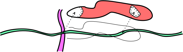
The second limitation is that when the lower passage does not completely fill the hole, it shows up as an ugly unrendered gap. This situation can happen when the pitch is sloping instead of vertical, so that the lower passage appears to stick out the side without connecting to the pitch, or it can happen when the passage at the bottom is narrower than the pitch opening at the top.

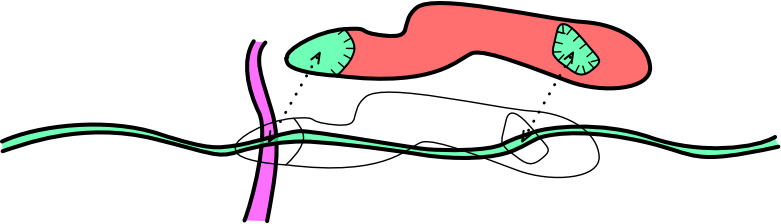
It depends on how perfect you want your map to be; should it represent reality, or should it use symbolic representations? You could just accept the poor rendering. You could shrink the size of the pitch opening and pretend that it is as narrow as the passage below. Or you could try to actually fix it. A common fix for this is to stretch the bottom passage to be as wide as the upper hole. To avoid confusion for viewers who visit the lower passage, the walls can be optionally drawn in using borders (or “wall” lines with “outline” set to “none”). In many cases, this works well enough, and would typically be the approach used.

However, this approach fails rather badly when using offset maps. When a map is offset, the upper passage again shows an unrendered gap, and the lower passage has a bizarre shape that can be very confusing for a visitor, who might expect to encounter a chamber which is not actually there, since the extra space is far above them at the top of the pitch.

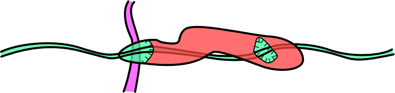
So rather than widening the lower passage, a better (but more laborious) fix is to create another scrap that perfectly fills the shape of the pitch opening. Set its survey station as the station at the bottom of the pitch, so it gets the right colour for its altitude. Use “wall” lines with “visibility” set to “off” so that they don't make the pitch walls thicker. Use “break” to stack it below the lower pitch in your map. When offsetting the upper passage, move the filler scrap too. Now the offset passage looks perfect.
However, when not offset, there is a slight flaw. The lower passage's colour gets painted twice wherever the lower passage sits on top of the filler scrap. It therefore obscures passages beneath it too much, and the colour of the passage is a little too strong beneath the pitch.

Imperfections like this are a little painful for perfectionists, but fear not because there is a better solution. When displaying the upper passage in its normal position, don't use a filler that completely fills the pitch opening. Instead, have a different scrap which only fills the gaps between the upper and lower passages. This can be made from multiple little outlines (again, “wall” lines with “visibility” set to “off”), depending on how many gaps need to be filled. When the upper passage is being displayed normally, include that scrap instead of the scrap that completely fills the holes. Again, use “break” to put it below the lower passage, since it will spill half way into the lower passage's walls otherwise. (The result in simple plan view can be exactly the same as the stretched lower passage approach.) When offsetting the upper passage, include the scrap that fills the pitch opening completely instead, and do not use the scrap that only fills the gaps between the passages. This requires two extra scraps, but allows the pitch to be displayed correctly in both regular and offset forms. Perfectionists will be perfectionists.
Following the lines above and below
When trying to create a scrap that perfectly matches the lines of the pitch above, the simplest approach is to get out a text editor, find the “line pit” that is the pitch opening. Copy and paste it into a new scrap that will be used for the opening filler. Set it as a “wall” instead of a “pit”, set its “visibility” to “off”, and do not set the “outline” option.
With more complex shapes filling gaps between pits and walls, however, the source editing approach becomes unmanageable. Instead, it becomes easier to create a new line in XTherion, and click on all the points that you need to follow. When filling gaps between upper and lower passages, it really helps to have line points wherever they intersect, so that you can aim for them perfectly with your new line. If the lines are straight, that is enough. However, with lines that have back (“«”) and (“»”) values for Bézier curves, you will need to manually copy the back and forward values for each and every point. Set “smooth” to “off” on each point of your new line so that they can turn sharp corners at those points if needed.
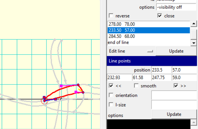
The important part here is to make sure you select the correct back/forward direction of each line you are trying to follow from that point. The line you are following may have been created in the opposite direction to the direction you are tracing, so you might need to use its back direction as your new forwards direction. When switching lines at a line junction, take your back direction from the first one, and your forwards direction from the second one. This is how the examples on this page were made. Have patience ;)
When the top and bottom of the pitch are in different surveys
If the top and bottom of the pitch were surveyed in separate surveys, or even different sketches (XVI image files), this task becomes much harder. The easiest method is to just approximate the position of the lines in the upper and lower passages, so that when you tell Therion to “join” the scraps (using the “join” command), the top and bottom pitch outlines line up closely enough that any alignment error is hidden by the “pit” line. As long as the pitch parts are rendered without using “break” to separate them, small overlaps will actually be hidden by the rendering. If there is a “break” between them, you will need to be a little more careful. If the sketches are hand drawn without precise scales, or if the XVI images are at different scales, or even if your loop closure error causes severe distortion, this is probably the only way to do it.
However, if your surveys have XVI images at the exact same scale as each other, you can be much more precise. Imagine that you need a line in the lower survey to follow a “pit” line in the upper survey. Firstly, create any walls of the edge of the passage that you will ask Therion to “join” at the pitch (but don't worry about the pit line yet). Slowly test and adjust them until they create a nearly perfect join without using the “join” command. Create the “pit” line in the upper survey (if you haven't done so already). Now to get the matching line in the lower survey; create a new scrap containing a matching line within the .th2 file of the upper survey, as described above. Save it, then get out a text editor. Find that scrap/line in the .th2 file of the upper survey. Cut and paste the line's definition into the .th2 file of the lower survey. Open the lower survey's .th2 file in XTherion's map editor. The line will most likely be in completely the wrong place, since it was set up with the upper survey. Move the line into the correct position, using the walls that you had carefully positioned as your guide for the desired position. The line should now be in almost exactly the right place, and should match the line in the survey above, perhaps with a little distortion. Move other lines as needed to connect with the new line.
Now that the lines match almost exactly, you can ask Therion to make them match perfectly. In the parent survey file, use a “join” command to join the scrap walls of the two surveys. Then - here's the perfectionist bit - use a separate “join” command for each linepoint of the “pit” line, and the matching line in the lower survey. After you have done that, they should always match exactly; even if Therion has to distort one, it will end up distorting them both the same amount.
join pitchtopSP@uppersurvey pitchbottomSP@lowersurvey
join pitchline@uppersurvey:0 bottomedge@lowersurvey:0
join pitchline@uppersurvey:1 bottomedge@lowersurvey:1
join pitchline@uppersurvey:2 bottomedge@lowersurvey:2
join pitchline@uppersurvey:end bottomedge@lowersurvey:end
Effects on LOX files
Many of these might cause LOX file output to produce unexpected results. For example, the versions that fill the gaps with the colour from the bottom of the pitch may cause unexpected “wings” to appear on the lower passage, when the width actually belongs to the upper passage.
Note, however, this did not happen when testing with the files used to produce these demonstrations. This may be because the survey did not have any splays, as the data was made up for the demonstration, rather than being real survey data. Therefore the LOX files were created with Therion making guesses about passage dimensions, which were much bigger than the sketches, hiding any “wings”. Instead, Therion projected the width of the upper passage all the way down to the lower passage, even if there were no scraps that filled any gaps. This meant that for these demonstrations at least, Therion would always create the same renderings, whether there were scraps filling the gaps or not.
In all cases, cutting out the “pit” with “-outline in” did not cause hollows to appear in the upper passage, because the LOX file is apparently generated from the outer “wall” lines of the survey, not from the “pit” lines inside them - the “pit” lines may just create a small indent in the LOX output, rather than shaping the passage.