Rigging topos
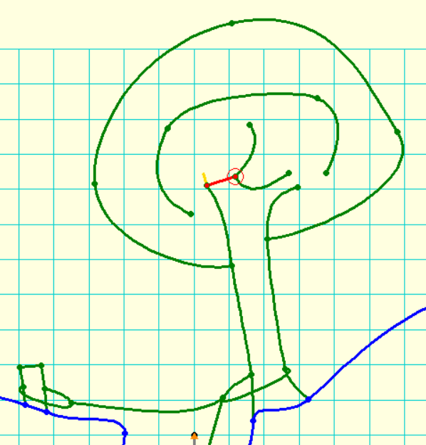
This article is based on the traditional rigging topo approaches and styles used in the UK. However, it is likely be to very similar to approaches used elsewhere, and the approaches can be adapted. The symbols used here were almost entirely made especially for the purpose of making rigging topos. The sample rendering shows a series of both explicit naturals (stalagmites, colums, flakes, boulders, trees, stakes, bars) and symbolic naturals (circle), explicit P-hangers and implicit hanger dots:

Rigging topos (rigging diagrams) would usually start their life as a projected elevation (see the Therion book and the Extended Elevations article for details). The walls can be drawn with regular wall lines. The surface can be drawn with whatever lines are appropriate (the example shows wall lines with “-subtype sand -outline none -clip off”), with linepoints to connect stakes and trees.
The ropes are drawn with “rope” lines, using Simplified rope lines. This is because the default Therion “rope” line tries to look pretty, but in doing so, it loses the control of what linepoints should just be corners rather than rebelays and what linepoints should have anchors. It has an all-or-nothing approach, which is not useful in a rigging topo, where each rope corner and anchor must represent an actual situation. In addition, the normal rope line often fails to draw all the rope parts (some go missing at the end of a line). The line can be turned into a rather thin line by enabling the “rebelays off” and “anchors off” option of at least one linepoint along the rope, but this is clumsy, and relies on you not editing it and accidentally removing it. The simplified rope lines code solves all these problems at once, by making a thick rope line that just behaves like any other basic line.
Each kink in the rope (like at the deviation) is created with a line point. Each rebelay curve is created with a line point just before it, with the » directional control enabled, and dragged to an appropriate point. The rebelay point has the line's « directional control enabled and dragged to an appropriate position to create the curve. The » is not enabled. For traverses, the « and » are both enabled, but without enabling the “smooth” option. Y-hangs are created with the rope continuing from one anchor point to the centre of the Y-hang, then down the pitch, while a second line is used for the other side of the Y-hang.
The hangers are created with P-hangers that face the right way, and other anchor designs. The “p” P-hanger version is used where it must attach perfectly to the walls in the aven to the right. The “ropedp” version is used for the P-hangers that are attached to a rope. The “fixed” version is used to represent any kind of hanger with a dot symbol, and the “natural” version is used to represent any natural belay with a circle.
The initial stake and bar are created with Shoring lines, with extra points to attach the tethers to.
The tree is created with Trees; 3 treetrunk and 4 bush lines. The trunk has linepoints on either side, used to attach the tether, and then further points to attach the bush.
Important features that will be encountered are drawn with rock border and rock edge lines. The drilled flake is made from a rock border for both the edge and the hole, with linepoints on each to connect the tether to. The stalagmite and column are made from rock borders (after all, that is basically what they are, so it is accurate), with extra line points used to connect the tether. The boulder, of course, is also made from a rock border, with points to connect the tether.
Tethers/slings are made with a rope line. It is curved with the usual bezier curve controls, with its first linepoint at one side of wherever it passes behind an object, a second linepoint wherever the rope must connect to it, and a final linepoint wherever it passes back behind the object. This approach means the rope can connect perfectly to it, and it always looks perfectly like it passes behind an object without gaps or rendering mistakes.

The deviation is made from Deviations line, starting at the flake's tether, and ending at the main rope's linepoint.
The traverse ledge is made with Pit lines that look different in elevation view.
The rope lengths are made with Rope lengths points.
The ladder is made from the standard Therion “fixed ladder” line. Although Therion has a “rope ladder” line as well, which seems to be the right symbol for a portable ladder that you rig for yourself, it does not have an actual definition so it does not work at the time of writing.
Shortening long passages
Rigging topos will typically concentrate only on the parts of the cave that need ropes, with only enough passage either side to identify the location. Long passages between pitches are normally shortened with a break symbol to indicate that the passage is longer than shown.
With Therion, this can be achieved in a few ways, but the easiest for horizontal passages is as follows:
Start with the extended elevation, with the “extend start” and “extend right” (or left) set as needed at the top of the first pitch. On reaching the first passage that needs to be shortened, allow one survey leg to continue into the passage. Then from the next leg, set all legs to “extend vertical”. This causes them to take up no horizontal space. Continue until one leg before the next pitch. Then set that leg onwards to “extend right” (or left) again. Export this as an XVI, create a new th2 file for it, insert the XVI image, draw your extended elevation scraps around it. Potentially, you could even draw this as one scrap.
extend start 1
extend right 1
extend vertical 6 7
extend vertical 7
extend right 22 23
extend right 23
Use the break line over the passage (with “-subtype break -clip off -place top” options) to indicate that it is longer than shown (usually used for passages that keep their dimensions fairly constant). Alternatively, draw it as two unconnected scraps, with a break line at each of the ends facing towards each other (usually used for passages that have dramatically changed size).
For passages that lose vertical height over the unwanted length (or if you just don't want to use the “extend vertical” approach), this is still fairly easy. It doesn't matter whether you have used “extend vertical” on the extended elevation or not. Create the scraps for each pitch. (You do not need to create scraps for the passages that you do not want to include.) The simplest way to combine these into a final PDF is to create a “map” for each scrap (or each group of scraps that can be treated the same as each other). Create a parent map containing those child maps. In that parent map, use offsets with “none” as their preview setting, to pull the maps of the pitches into the desired location.
map toppitches_map -projection extended
  pitch1_scrap
  pitch2_scrap
endmap
map bottompitches_map -projection extended
  pitch3_scrap
endmap
map topo_map -projection extended
  toppitches_map
  bottompitches_map [-30 107 m] none
endmap
When you export that parent map (topo_map in the demo) as an extended elevation, it will position them in the chosen positions.
Alternatively, you can just select each pitch map in turn (toppitches_map and bottompitches_map in the example), and export them as PDFs. Then create a new PDF export that uses “map-image” to import each of those PDFs in turn, positioned where you want them in the resulting PDF.