This is an old revision of the document!
FAQ Thinking in Therion
Surveys and Drawings
How to enter centreline?
The basic building block is the centreline command. If the cave is larger than a few meters it’s a good idea to split the data into more than one file and separate centreline data from map data.
We usually use one *.th file containing centreline per survey trip. It’s handy to start with an empty template file as shown below, where the dots will be replaced with appropriate text.
encoding ISO8859-1
survey ... -title "..."
  centreline
    team "..."
    team "..."
    date ...
    units clino compass grad
    data normal from to compass clino length
      ... ... ... ... ...
  endcentreline
endsurvey
To create a unique namespace the centreline command is enclosed in survey … endsurvey commands. It’s useful when the survey has the same name as the file which contains it.22) The points will than be referenced using the '@' character — see the survey command description.
For really large caves it’s possible to build a hierarchical structure of directories. In such a case we create one special file called INDEX.th which includes all other *.th files from given directory and contains equate commands to define connections between surveys.
How do I specify a main entrance, and also the other entrances?
And how do I obtain outputs that contain only 'caves' (main entrances), and then outputs that contain both 'caves' and secondary entrances?
The main entrance and cave name is defined, by specifying a survey station closest to that entrance, with the survey definition. Usually you will do this where you define the survey that collects together all the trip surveys (preferred), but you can also do this in any of the trip surveys as well (although 'caves' will be more deeply nested into the reported survey hierarchy).
 survey Growler -title "Growler Cave" -entrance 1.3@01
   ...
 endsurvey
The Therion Book says,
“-entrance <station-name> ▷ specifies the main entrance to the cave represented by
this survey. If not specifed and there is exactly one station marked entrance in this
survey, it is considered to represent a cave also. This information is used for cave-list
export.”
As well as in export cave-list outputs, the information is also used in export model and export map .kml outputs.
Within the survey, or a sub-survey (trip survey) centreline, you can define secondary entrances, by specifying station arguments.
centreline
  ...
  station 1.17 "Second Entrance" entrance
  station 1.42 "Top Entrance" entrance
  ...
endcentreline
Now you can export hierarchically structured cave-lists in html, kml (Google Earth) and txt formats. For example;
#html  (& txt is similar)
export cave-list \
  -surveys on   \ # on = show survey, cave hierarchy, & entrances so long as location is on,
                  # off = show caves only, not entrances, no hierarchy
  -location on \  # on = show cave coords, and entrance coordinates only if surveys are on
                  # off = no coordinates
   -output ./Output/RiwakaSystemCaves.html
#kml
export cave-list \
  -surveys on   \ # on = show survey, cave & entrances hierarchy
                  # off = show caves only, not entrances, no hierarchy
  -location on \  # on|off = no difference
  -output ./Output/RiwakaSystemCaves.kml
There is also a cave-list dbf format, however that does not seem to include the hiearchy.
TO BE CONTINUED FEB2018
See also Outputs - Lists and Export selection and Formats page
And in the Therion Book see Lists - Caves, surveys, continuations page 63, and 'Listing Caves' pages 87-88 (version 5.4.1)
How do I draw maps?
The most important thing is to decide how the cave is divided into scraps. The Scrap is the basic building block of the map. It’s almost always a bad idea to try to fit each scrap to the corresponding *.th file containing the centreline from one survey trip. The reason is that connections between scraps should be as simple as possible, and surveys often start/end at junctions. Scraps in general are independent of the centreline hierarchy so try to forget the survey hierarchy when drawing maps and choose the best scrap joins.
We recommend inserting maps in the last-but-one level in survey hierarchy. Each scrap may then contain arbitrary parts of any survey in the last level of hierarchy. For example, there is a survey main which contains surveys a, b, c and d. Surveys a – d contain centreline data from four survey trips and each of them is in a separate file. There is a map main_map which contains scraps s1 and s2. If main_map is located in the main survey, scrap s1 may cover part of the centreline from survey a, complete survey b and part of c; s2 will cover part of the a and c surveys and a complete d survey. The survey stations names will be referenced using the '@' symbol (e.g. 1@a) in the scraps.)
Scraps are usually stored in *.th2 files. Each file may contain several scraps. To keep data well organized, we have some naming conventions: in the file foo.th2 all scraps are named foo_si, where i is 1, 2 and so on. Cross-sections are named foo_ci, lines foo_li etc. This helps a lot with large cave systems: if some scrap is referenced, you immediately know in which file it had been defined.
Similar to *.th files, there may be one file INDEX.th2 per directory which includes all *.th2 files, defines scrap joins and maps.
Here is my interpretation of the above described Therion survey namespace and map hierarchy. (Let me know if I got it wrong. There is a good chance I have. Bruce)
FILE: main.th (an INDEX file for surveys which comprise the cave called “main”)
  survey main
     centreline
           input a.th         # trip file containing a single trip survey
           input b.th
           input c.th
           equate 25@a 1@b    # identify which stations are equal
           equate 56@2 1@c
           input main_map.th2 # reference the file described below
     endcentreline
  endsurvey main
ENDFILE:
FILE: main_map.th2 (an INDEX file for maps which depict the cave called “main”)
  input foo.th2      # a drawing file that can reference stations from any or all of the surveys a, b, c
  input goo.th2      # can also reference stations from any or all of the surveys a, b, c
  map main_map
           foo_s1    # a scrap from file foo.th2
           foo_s2
           foo_s3
           break     # foo passages pass over top of goo passages
           goo_s1
           goo_s2
           goo_s3
           goo_s4
           goo_s5
 endmap main_map
 join foo_s1 foo_s2 # join any of the scraps from the above files that don’t do so automatically
 join foo_s1 goo_s5
ENDFILE:
When drawing scraps you should check if the outline is properly defined: all lines creating the outer border should have -outline out option; all lines surrounding inner pillars -outline in option. Scrap outlines can’t intersect themselves — otherwise the inner side of the scrap can’t be determined. There are two simple tests that scrap outline is correct:
- there is no METAPOST warning ”scrap outline intersects itself“
- when you set passage fill to any color (color map-fg <number> option in layout), you may see what Therion considers to be inside of the scrap.
See also the drawing checklist
How do I create models?
A model is created from scrap outlines. The height and depth of the passage are computed from passage-height point map symbols. In the future, there will be a dimensions map symbol which will allow more precise floor and ceiling height specification.
How to adjust background image
How to access lines or points on top of each other?
Currently if an area crosses a scrap join we just put an area either side - one in each scrap. This needs a 'border -subtype invisible' line across the passage at the join on _both_ scraps - these lines are directly on top of each other. The problem here is that you can't click on the line which is 'below' so you can't complete one of the areas without first moving the top line to the side temporarily. This is clearly not satisfactory. Is there a better way? If not then selecting the new scrap should move the border line to the 'top' for the purpose of clicking.
Did you try right-click on the line point? Each right-click changes the line used for editing if there are more of them on top of each other.
How do I join three scraps in a Y-shape?
Let us say we have three scraps going from one survey point - Y or T-shape
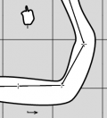
If we connect such scraps in the 'normal' way - the result would be a triangular hole in the connection (rectangular, if there are four scraps, etc). We may use a virtual wall with the '-visibility off' option to fill this hole, but it is much simpler to use a trick - add a small section of wall to one of the scraps where the two others scraps are joined. See attached pictures.
Xtherion “normal”:  pdf “normal”:
  Xtherion “tricky”:
  pdf “tricky”:
 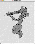 Click on picture to see original size
see also joining_scraps_together
How do I move an object from one scrap to another scrap?
Only do this when you have no choice. It is much better to design the layout of scraps so you never need to move this around.
If both scraps are in the same .th2 file:
- select the object you want to move.
If you want to move a part of wall you should split it first:
- select the point in which you want to split the line
If both scraps are in different .th2 files:
You may do it with caution in text editor. You may use id option in object control section to help identify the correct object.
How to draw complicated junctions?
There are a couple of places where there are 'gaps' in the grey background. The most obvious example is the large chamber in the middle is foo_s2 (with lots of boulders). The main chamber has a RH wall which is in the 'middle' of 3 walls. The rightmost wall is the RH wall of a lower passage, formed by the large pile of rocks in the middle separating the upper and lower parts for 30m or so. What is the 'therion way' to draw something like this? Just use a border for the central line? Or split the lower portion into a very small scrap, I suppose? And there is a similar problem on the other side of the chamber (where a steep ramp goes up on the left)
The separate scrap is the best solution. The other is to split the inner wall and set the 'outline in' option as displayed in the attached picture.
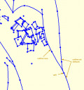 click on image to see original size
The exact rule is that each line forming the outer border of the scrap has to have 'outline out' option (walls have this by default), each line forming inner pillars 'outline in' option, and all other lines (even walls lying inside of scrap) 'outline none' option. For all walls which shouldn't form the scrap border you have to set 'outline none' option. See the second attachment to see how to specify this.
 click on image to see original size
How to draw "transparent" pit?
There are two underlying rooms connected with a large pit. If you draw raw overhang and pits lines you will receive a bit strange looking picture:
 Click on picture to see original size
If you set the options for overhang and pit lines to: -outline in -clip off, the pit will be transparent:
How to change the size of title font on map
Check the TherionBook - you have to add to your layout:
code tex-map
\legendcontent={%
  \hsize=\legendwidth
  \ifnortharrow\vbox to 0pt{\line{\hfil\northarrow}\vss}\fi
  \edef\tmp{\the\cavename} \ifx\tmp\empty \else
    {\size[26]\the\cavename} \vskip1cm
  \fi
  \ifscalebar\scalebar\vskip1cm\fi
  {\rightskip=0pt plus 3em\parskip=3bp
    \edef\tmp{\the\comment} \ifx\tmp\empty \else
    {\size[12]\the\comment} \par\medskip
    \fi
    \everypar{\hangindent=2em\hangafter=1}
    \edef\tmp{\the\cavelength} \ifx\tmp\empty \else
      {\size[12]\si\the\cavelengthtitle: \ss\the\cavelength\par}
    \fi
    \edef\tmp{\the\cavedepth} \ifx\tmp\empty \else
      {\size[12]\si\the\cavedepthtitle: \ss\the\cavedepth\par}
    \fi
    \edef\tmp{\the\exploteam} \ifx\tmp\empty \else
      {\size[12]\si\the\explotitle:
\ss\the\exploteam\quad\si\the\explodate\par}
    \fi
    \edef\tmp{\the\topoteam} \ifx\tmp\empty \else
      {\size[12]\si\the\topotitle: \ss\the\topoteam\quad\si\the\topodate\par}
    \fi
    \edef\tmp{\the\cartoteam} \ifx\tmp\empty \else
      {\size[12]\si\the\cartotitle:
\ss\the\cartoteam\quad\si\the\cartodate\par}
    \fi
    \edef\tmp{\the\copyrights} \ifx\tmp\empty \else
      {\size[12]\ss\the\copyrights\par}
    \fi
  }
  \formattedlegend
}
where you may replace the size of font - “default\size[26]” before “\the\cavename”.
How to arrange the maps
Here is a part of .th file with survey, input and map definitions
survey rotunda_perlovy -title "Cachticka jaskyna, Rotunda + Dom starcov"

  input ../rotunda_dlhy_hlboky/rotunda.th
  input ../rotunda_dlhy_hlboky/dlhy_dom.th
  input dom_starcov.th
  input bordel.th
  input oranzovy.th
  input perlovy.th

map rotunda_perlovy.map

  perlovy.map@perlovy
  oranzovy.map@oranzovy
  break
  #rotunda.map@rotunda
  break
  #dom_starcov.map@dom_starcov
  break
  #bordel.map@bordel

endmap
As you may see, there are several files inputed to this survey and there are several maps, some of them commented. When you use thconfig file without “select” command, the final map will include all partial maps, doesn't matter if they are uncommented or not.
endlayout

export map   -o rotunda_perlovy.pdf   -layout my_layout
The reason is, the maps definitions are in the included files and configuration file will use all of them.
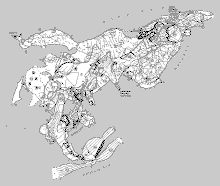 Click on picture to see original size
If you want to generate map with only two submaps - perlovy.map and oranzovy.map - you should use “select” command in configuration file and select the rotunda_perlovy.map. Therion will generate the map with only perlovy.map and oranzovy.map now.
endlayout

select rotunda_perlovy.map@rotunda_perlovy

export map   -o rotunda_perlovy.pdf   -layout my_layout
 Click on picture to see original size
If you uncomment all the submaps in map definition you will receive the next map:
map rotunda_perlovy.map

  perlovy.map@perlovy
  oranzovy.map@oranzovy
  break
  rotunda.map@rotunda
  break
  dom_starcov.map@dom_starcov
  break
  bordel.map@bordel

endmap
Note: the break command coerces dividing the maps to appropriate levels. Without break command all the maps would be in one level. Check the situation on left side of pictures - the presumed walls.
 Click on picture to see original size
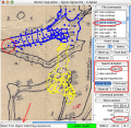
There are three very useful buttons in compilation window menu - Survey structure, Survey info and Map structure. You may use the Map structure information to easy select the maps or submaps to your configuration file - just doubleclick on map you want to select and it will be copied to your thconfig file
Click on picture to see original size
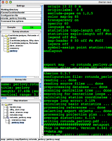 Survey structure and Map structure
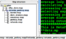 Map structure with all submaps uncommented
How to draw cross-sections
The cross-section scrap must have option ”-projection none“. It must be calibrated - see “How to add old 'lost data' survey to some new data?”
Section lines - they must be of type “section”
Point “section” - it defines the place where the cross-section will be drawn. There is an optional parameter -align [tr, tl, br, bl] - the TopRight option means the section rectangle will be drawn in TopRight quadrant of the point.
Both line “section” and point “section” belong to plan or elevation scrap.
–If you draw only segment line, without control points, you get the solid line crossing the passage - the arrow could be added by “direction” option.
–If you prefer lines only by sides of passage you should draw line as a curve, with control points on both sides. The control points will control the length of visible segments of section line.
Click on image to see original size
And …
 drawing/scaling the cross section itself
  to set these numbers
How to add old 'lost data' survey to some new data?
Let us say I have a survey on a piece of paper, but the centreline data has been lost, and I know nothing but the distance that corresponds to 50m. How would I go about therionising this survey?
- Scan the survey.
- For each scan define one virtual station (e.g. the last point from known survey), that will position this scan in real world coordinates.
- For all scraps on this scan, I would insert into each of them only this single station (and I would give it
-visibility offoption, that it will not be visible in the map). - Scaling and rotation of scrap would be done using
-scaleoption. If you have a horizontal 50 m scalebar on the paper, and the page/scan is facing north, than I would use0 0 50 0as the real scale coordinates for the ends of the scalebar. See attached pictures. Real coordinates are not important, only their difference (vector) is. Scrap will be positioned according to stations specified in it.

 Click on picture to see original size
All you need to do is to specify a paper/scan and real vector. From these two vectors the rotation and scaling are determined.
And would I then just copy those numbers to all the other scraps?
Yes, for all scraps lying on the same scan, these numbers would be the same.
I have no idea how to give these numbers. Which way do they increase?
Both paper/scan and real coordinates are standard cartesian. X = east, Y = north.
Are both sets of numbers entirely arbitrary and only the ratio matters?
Yes, the numbers are arbitrary, only the relative positions are important.
Are there overflow limits I should worry about?
There are no overflow limits - you can probably use any numbers you like.
- When drawing the scraps, I would then adjust the positions of those virtual paper/scan stations, so that the scraps will match as closely as possible. When the scraps match up reasonably well - then I would join them. And that's all. You will need only one station for each page/scan.
Mixing projections, or calibrating scraps only using scale option I do not consider as a good idea. If you decide to use other coordinates (e.g. GPS), then you will need to shift all pages/scans somewhere else. If the real coordinates are in the form:
fix paper1 10 20 30
fix paper2 20 30 40
then it will be very simple, because it is in one table. If the scaling points were in the scrap headers, then it would be very hard, as they will all have to be changed individually.
Another point - this way (one station per scrap or page) each scrap also receives some vertical information. This will allow you to color scraps by altitude, it will be also possible. When scaling scraps only using -scale option, there is no vertical information.
How do I print only cave or surface stations with a particular mark (ie fixed or painted)
From a 2012 forum post…
The problem is, that there are multiple “attributes” and therion supports only hide or show for single symbol attribute type at one time. Therefore, specification is tricky. In this case, this is what you can use:
symbol-hide group centerline    # 1. hides all centerline symbols from everywhere (stations and shots).
symbol-show point cave-station  # 2. tells therion, that you want to show stations in the cave. But in fact point cave-station itself does not show any symbol. It only specifies, that stations in the cave should be shown rather than surface stations.
symbol-show point station:painted # 3. Now specify, that you want painted and fixed stations to be shown
symbol-show point station:fixed
In fact, if you use symbol-hide group centerline, and want to show some station afterwards, you need to specify explicitly both, whether you want to show stations in cave or on surface AND which kind of stations you want to show. You can use also symbol-show point station to show all kinds of station subtypes that can be set in centrelines. ie
mark temporary
mark fixed
mark natural
mark painted
And now I am not sure, whether I understand my self ;)
But at least, this configuration seems to work on my data sample. It would be great to have some kind of query language, show/hide/color for symbols…
Here is another forum post with a metapost approach a similar problem http://article.gmane.org/gmane.comp.gis.therion/2883 <link is broken>
How do I find out what the available symbols look like?
A sample dataset that produces a map demonstrating areas for each of the built-in symbol sets can be found at all_areas_all_symbol_sets
How do export centerline only?
There are two types of maps definitions - one from scraps and other maps and second only from surveys. There is not possible to combine these two definitions in Therion.
  survey index_survey -title "Perlová jaskyňa"

  input 2015.th
  input 2016.th

  equate 48@2015_survey    0@2016_survey

  map polygon.map -projection plan
  	2015_survey
  	2016_survey
  endmap

  endsurvey
The thconfig file must contain the “select” command with full path specified. The best way how to do it is double-click on appropriate map in map structure chart in command column.
  source index.th

  select polygon.map@index_survey

  export map -layout-debug station-names ### to display station names too.
Concepts and Terminology
What constitutes a "pillar" in therion?
I think we need a better understanding of what makes a 'pillar'. I thought
a pillar was a closed loop within a passage, but the enclosed area in the picture below is not a closed loop
(a passage goes off underneath from the gap). So when does therion need to be told that an outline is 'in'?
Nobody would call the massif between two passages in a cave a 'pillar', but therion sees things purely
geometrically – it doesn't
matter if a closed loop within a passage is small or large, formed by a
fallen block or two passages. So everything surrounded by a scrap border
and not belonging to the scrap is a 'pillar' and need to have the -outline
in option specified for the walls.
This picture illustrates the above case. The red and cyan lines have to have ”-outline in“ option specified.
 Click on image to see original size
There is another problem. Even if scrap boundary has correctly specified all -outline out/in/none options, there may be problem to determine which area is inside of the scrap if the outline crosses itself (like figure 8). In such a case you get a MetaPost warning
Warning: scrap outline intersects itself in foo_s1@foo
and it is than random if MetaPost determines the interior of scrap correctly. The solution is to
- find where the loop occurred – this may be tricky, but start with the endpoints where scraps should join. The loop may be very small, even unnoticeable. Even worse, it may not be visible at all, because it happens only after the joining of scraps – which is the case of example :(
- correct the position of the control points (see the second picture)
The enclosed pictures make it more clear.
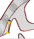
 and correction –>
 Click on image to see original size
I have a bit of a problem with your example fix. Now the wall does not follow the wall on my survey - I have had to distort it a little to solve this problem. This seems to me to be the wrong answer - the original version is a correct drawing of the cave, therion needs to be able to join (and distort if necessary) that drawing without telling me it it 'wrong' and I have to draw the cave a slightly different shape in order for it to be accepted.
There is a problem that therion does some calculations itself and some lets to MetaPost. When the scraps are joined, therion has no idea if the border is intersecting itself. When MetaPost examines the border, it's too late for changing the scrap distortion – it may only give a warning.
I realise this may not be easy, but I don't really think that telling the user their correct drawing causes an error is good enough. Perhaps when the outline intersection happens on a line that is a scrap end line (i.e one that therion invented, not one the user drew) then that should not be an error
It can't be just ignored, because metapost needs non-intersecting outline to determine the interior of scrap correctly.
and therion could adjust its own line to compensate? Is that practical?
It can't right now – the intersection is detected only in metapost. We would have to implement the algorithm in therion, which would be not trivial.
Projections, plan, elevation, extended and none
Plan Projection
-projection plan
A view of the cave as viewed from above, orthographic, without any perspective distortion
Elevation Projection
-projection [elevation 290 deg]
A view of the cave as viewed from the side, orthographic, without any perspective distortion. You can make any number of elevations each viewed from different directions. In this example the elevation is looking in the direction of bearing 290 degrees. If there is a coordinate system or declination specified it will be a grid or true bearing, otherwise it will be a magnetic bearing.
Extended Projection
-projection extended
Imagine the plan view of the cave straightened so that all of the passages lie on a single line from left to right (or vice versa). Now imagine viewing this straightened cave from the side - this is an extended elevation (often called a developed, or unrolled elevation). The passages are all shown with their true slope as you would experience it travelling through the cave. Very good for producing a route guide elevation for a vertical cave. Check out Extended Elevations page.
None Projection
-projection none
For drawings that fit none of the above, typically cross sections of passages.
Is it possible to mix projection ''none'' and ''plan'' in a map (and have joins between them)?
No it is not. In the map - all joined scraps have to be from the same projection.
What do the "scale" and "base-scale" options in layout section of thconfig file mean?
If the base-scale is the same as the scale, it has no effect (such as 1:1 photocopy).
If there is for example “scale 1 200” and “base-scale 1 100” the symbols and text will be printed in 1/2 size because of base-scale setting.
If you printed the survey at 1:1000 and photoreduced it to 1:2000, the symbols and text would be halved in size by the photoreduction. Just printing at 1:2000 will give symbols and text twice as large as this, so changing base-scale from 1:1000 to 1:2000 doubles the symbol and text sizes in the same way.
You may forget the base-scale if the default settings work well. We introduced the base-scale to make it possible to do simple adjustments to the size of symbols used without the need of metapost programming (e.g. when symbols appear too big in the 1:400 scale, but OK in 1:200 scale, it's sufficient to set “base-scale 1 200” and “scale 1 400” and I get map in 1:400 scale with symbols proportionally as large as on 1:200 map). If therion gives you suitable symbol sizes, then just use the scale setting. If not, experiment with base-scale or redefine metapost.
Explain Outputs Exports Selections Formats
Troubleshooting
What does "error -- cp exit code -- 1" mean?
Typically one of three causes.
One cause is having a previous version of an exported output file open with Adobe Reader when Therion's compiler is trying to overwrite that same file.
(Possibly happens with other viewing software as well. Foxit's Pdf Reader does not cause this problem, but you will need to reload the file to see the new version of course).
Another cause is trying to export a file to a folder that does not exist.
For example, the following will cause this error if ./Output does not exist. Therion is very case sensitive, so ./output will trigger this error. It will also trigger the error if FloraCavesPlanMap.pdf is already open in Adobe Reader
export map -projection plan     \
  -layout LayoutMapThisCave     \
  -layout LayoutMapThisCavePlan \
  -output ./Output/FloraCavesPlanMap.pdf
And if the size of the pdf page will exceed about 5.5m, you also get;
!  ==> Fatal error occurred, no output PDF file produced!

##################### end of pdftex log file #####################
D:\Program Files\Therion\therion.exe: error -- pdftex exit code -- 1
What does "error -- cp exit code -- 2" mean?
This seems to mean there has been an error reported by metapost, and so should only occur if you have been tinkering with metapost, or perhaps a bug in the default therion code.
Look for any errors that may have been reported by metapost further up in the therion.log file for a clue.
What does "error -- metapost exit code -- 3" mean?
I get this from time to time, again a metapost error - see the answer to metapost exit code – 2 above to track it down.
How do I find duplicate or incorrect survey points?
The easiest way to examine stations is to put -name in the search field.
Then click “Find first” and then “Find next” and check each station, to see whether it has the correct name and position, and is associated with the correct scrap.
Click on picture to see original size
How do I move an object created outside a scrap?
If you create an object outside the scrap … endscrap construction, you can use Move up, Move down or Move to buttons in the map editor window to move the object to the desired place. See the attached picture.
 Click on image to see original size
How do I use Debug Mode in Layout? Visualising drawing errors and distortion
If your map is coming out distorted or joins are not connecting in the right place then debug mode is a very useful way to see what is going on. Indeed it is generally useful to get a visual display of the distortions in the map.
You turn it on by putting debug on or debug all (which each have the same effect) in your layout command for the map. The default is debug off.
You can also choose individual debug components, for more refined control; ie
debug first # first transformation, red lines - scrap rotated and scaled only
debug second # second transformation, blue lines - scrap morphed according to station positions
debug scrap-names
debug station names
This enables you to obtain only the particular information you require.
layout debug
  debug on  #or debug all
  ...
  ...
endlayout

export map -proj plan -layout debug -o debug.pdf
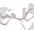
This will produce a map which, as well as the finished result, also contains red and blue outlines, various coloured points, and yellow and black lines indicating distortions. The meaning of these is as follows:
- red-lines - original scraps just rotated and scaled
- blue-lines - scraps adjusted to survey stations (before processing joins)
- red points - original positions of survey stations
- yellow points connected by yellow line - original position of two points in scrap with maximal distortion
- black points connected by black line - final position of two points in scrap with maximal distortion
- orange points - the points with distance changed most during transformation
- yellow lines connecting black and yellow points indicate how these points were shifted
If there is only one black point this indicates two stations with different names at the same point.
 Click on picture to see original size
So how do we convert all these dots to a more meaningful understanding of scrap distortions?
- The size of the maximum distortion (for a scrap) is proportional to the distance between the black point from it's corresponding yellow point (black and yellow joined by yellow).
- If the black points are obscured under the corresponding yellow points, then the maximum distortion is not very much at all.
- Spacing of matched pairs of yellow points, or black points is of little significance, perhaps it is an indication of the size of area in the scrap that has 'maximum distortion'.
We can create a special layout to hide distracting features, and emphasize the debug characteristics we are interested in.
layout LayoutDistortion
## experimental Bruce Mutton 26Feb2017
## Hides most objects and emphasises maximal drawing errors (but not necessarily survey loop errors)
## Yellow/black spots indicate maximal distortion of scrap

## Enforce white background and passage infill to reduce visual confusion
  colour map-bg 100 #white
  colour map-fg 100 #white
  symbol-colour group all 80 # 1 = black symbols, 80 = light grey
  colour preview-below 80
  colour preview-above 80
  ## Consider invoking 'maps off' in your thconfig file to suppress offsets and previews due to map definitions
  opacity 10 #mostly transparent

  debug all #turns on all debug options, for visible entities only
  #or for more refined control...
  # debug first   # red lines
  # debug second  # blue lines
  # debug scrap-names
  # debug station-names

## Options to control text size
  ## Use scale base-scale pair to control text size ratios 2:1 to 10:1 OK
  scale 1 1000
  base-scale 1 200
  #set base-scale to smaller number to reduce text size (but increases relative yellow/black dot size)

## Hide features we don't want to see
  symbol-hide group all  #hides ALL except passage infill colour, and preview-above, below
  symbol-show group cave-centreline
  symbol-show group surface-centreline
  symbol-show line map-connection
  symbol-hide group text

## If all rows below commented out, only these entities visible;
## - centreline and yellow/black spots
## - scrap names
## - full centrelines and all station names for only those centrelines included in a map definition

  symbol-show line wall #this adds scrap outlines and red/blue morphing lines to output

  # symbol-show point cave-station #optional, sets up for showing cave only
  # symbol-show point surface-station  #optional, sets up for showing surface only

  # symbol-show point station #shows and labels all stations and red debug spots
  # symbol-show point station:fixed #shows and labels fixed stations only and red debug spots

endlayout LayoutDistortion
TO DO: Add some pictures
See also how_to_solve_the_incorrectly_determined_interior_of_the_scrap below
How do I find miss-drawn holes in scraps?
Each scrap defines a piece of cave passage, which (almost) always is defined by walls, being the boundary between a rock mass and the open space of the passage. There will be open ends of scraps, with no walls, where the open space (passage) continues beyond the scrap.
If these openings are very wide, then you may have to close the opening with a wall line with -visibility off or -subtype invisible.
If you want to draw a wall 'inside' a scrap, you must disable its passage defining properties, by setting -outline none.
If you follow these rules, Therion can correctly determine what is 'cave' and what is 'rock'. Sometimes it is a bit tricky, especially if adjacent scraps are 'joined' and as drawn they overlap or have significant gaps (you should never do this intentionally).
If you get it wrong, you can get significant distortion and incorrect colouring in your 2d and 3d outputs.
Here is a layout that you can apply to your export statement. ie export map -output cave.pdf … -layout LayoutCheckScrapsForHoles
layout LayoutCheckScrapsForHoles
## Martin Sluka Nov2019
## Hides most objects and emphasises passage interiors and walls
  symbol-hide group all
  symbol-show line wall
  debug station-names
  debug scrap-names
  colour map-bg 85
endlayout LayoutCheckScrapsForHoles
Here is what it looks like. Grey areas inside or between scraps mean there is a problem that you need to fix.
 Click on picture to see original size
How to solve the incorrectly determined interior of the scrap
Warning: scrap outline intersects itself in bmb3_s3@fake.
I have this warning in a few scraps in that survey - I wondered how serious it was, and what I should do about it. But without more details of _where_ it intersects itself (and why this is a problem), I could not do anything but ignore it.
The only information we can give here is the scrap name. There is no way how to find out in MetaPost where exactly the closed path intersects itself 
I have several more scraps which I cannot include in the overall survey at the moment because if I do I get cryptic metapost errors. We have to work out a way of getting better feedback to the user about _where_ the problem lies as it is currently extremely difficult to fix as you don't know which of many lines is at fault.
We think it's doable to give a line number in th2 file where the error occurs. It would be perhaps possible to also identify area border lines which don't intersect.
How did you find the above problem. If I understood the process you used to find this it might help me next time.
We got this error (incorrectly determined interior of the scrap) long time ago in Dead Bats Cave map. There was some strange clipping by the scrap border, which we couldn't explain. In that time there was no MP warning, no map colouring. We don't remember exactly but it took quite long till we identified that the problem is in the border and than what is wrong with the border. After reading thoroughly the appropriate chapter of the Metafont book we knew that problem is in the loop – but even than we couldn't find any – so small it was, in fact very similar to yours.
We added the MP warning to point to this problem. When we see it now, we first check scrap ends if something could cause the problem. The biggest problem is if the loop is introduced only after morphing the scrap ends before joining scraps. We can only recommend to move control point in the last bezier arc of wall just before the scrap end, run therion, undo the change by pressing Ctrl+Z and repeat with other walls until the problem remains.
The loop may occur also in the middle of the wall, but it should be visible, at least in 400% zoom.
We are sorry that there is no cleverer algorithm to find the loop :(
see also What constitutes a "pillar" in therion?
(There are some other scrap drawing tips in Avoiding Invisible or Misshapen Scraps in Loch and Google Earth)
This warning can sometimes happen if you have two wall lines joining on a single point, where Bézier curve controls pull the lines into a very acute angle (where the “back” facing Bézier controls are pulled beyond the arc of the other line). The solution is to reduce the angle of the join, or insert more linepoints so that the angle can be produced without needing to use Bézier controls to pull the lines so far that Metapost thinks they overlap. Check any such places in your scrap outline, and test whether removing the Bézier back or forward controls fixes it. If so, then this is the location of your error.
It can also happen if you have inserted a point along a wall line, with its Bézier controls oriented backwards compared with the rest of the line, so that the backwards one points forwards, or vice versa. The rendering looks normal, but Metapost has had to flip the orientation of the line twice, so it complains.
It can also happen if you have accidentally added two linepoints at the same location - this also causes Metapost to flip directions in order to get from one point to the next. Step through each linepoint in turn (in the “Lines” section of XTherion), and see if two ended up in the same place.
It can also happen on a closed wall line, when the ends join, and you pull the wrong Bézier control past the junction - this causes a combination of the two problems mentioned above.
How to solve strange errors?
It seems that if I include any of soundriver2_s1 soundriver3_s1 or soundrivercrab_s1 then it breaks. soundriver2_s1 is particularly perplexing as it is a straight bit of passage with no areas in it, 3 stations, and not much detail - seems to me there is very little to go wrong.
I'll start with easier problems. The problem in soundriver3_s1 was really tricky. Step by step description:
uncommented soundrivercrab_s1:
I got an MetaPost error
"! Paths 6 and 5 don't intersect."
It's always related to areas so I used “search & select” in the map area to find all areas. There was only one area (line 6 in File commands). I looked to Command preview window to see the definition and tried to locate all area border lines in the scrap. There was one line too much (l26-1164-70), which I deleted in Area control.
uncommented soundriver2_s1:
I got an error:
l_flowstone->...as>dlzka+(mojkrok/3);t1:=t2;endfor
                                                ;
l.5074 ))
         ;
The `angle' between two identical points is undefined.
I'm zeroing this one. Proceed, with fingers crossed.
The first error line gives the name of symbol in which the error occurred (l_flowstone) with a piece of its definition (which is not interesting now) and the second line gives a line number in the metapost file (created from all scraps) where the error occurred and the text on that line.
I knew that problem was in some line flowstone symbol so I used “search & select” to find all “line flowstone” occurrences, and checked the definition in the “Command preview”. Fortunately already the first flowstone line had duplicated point
703.0 793.0
703.0 793.0
I deleted it in Line control→Edit line→Delete point
uncommented soundriver3_s1:
Similar error:
l_arrow->...d(angle(direction.infinity.of(EXPR0))-90)shifted(point.infinity....l.5728 ),2)
         ;
The `angle' between two identical points is undefined.
I'm zeroing this one. Proceed, with fingers crossed.
As before I searched for the given symbol (line arrow): search & select line arrow (Find first, Find next, …) and watched the Command preview window to see the definition. I suspected that problematic is line 24 in the File commands window:
363.0 573.5
363.0 573.5 317.0 604.5 295.0 642.5
with the control point of bezier line equal to previous point. After playing a bit with control points and even deleting the line the problem remained. I couldn't imagine which arrow causes problems so I had to identify it according to the line number given in MP error.
I run therion in debugging mode (-d argument), opened the file data.mp in the $TEMP/thTMPDIR directory and jumped to line 5728.
The problem with the file data.mp is that it doesn't contain original coordinates from th2 files so I couldn't identify the arrow using coordinates. I counted how many arrows are in the scrap containing line 5728 before the arrow ending on line 5728. Our arrow was the second in this scrap. Metapost file has reverse order of symbols (in order to display first object in the th2 file on top) so the final result is that problematic arrow is last-but-one in the file, i.e. line 23 in the File commands window.
There is actually nothing wrong with that arrow – that is the reason why it took so long to find it :) It has the last control point identical with the last point, which is perfectly acceptable in metapost. Unfortunately there is some bug in the arrow definition, which doesn't allow this. I hope it will be possible to fix it. In the meantime you may change the line either to a straight segment (no control points) or add a control point different from the endpoint.
What are the limits for map and for atlas PDFs?
A scale is a problem in map mode (page larger than PDF and pdfTeX can manage – more than about 5*5 m), but there are no limitations in atlas mode and SVG map size.
An additional limitation is the size of a picture, which can metapost process – it's about 2.8 m. Each scrap is processed separately in one picture, so it means, that each scrap must be smaller than 2.8 * 2.8 m _in the output scale_. We don't think it's a big issue unless you try to draw the whole cave in one scrap. (At 1:100 scale a scrap can contain 280*280 m section of the cave).
How to find where a Metapost error is occurring?
See also What does "error -- cp exit code -- 2" mean
(the number 33 is just an example):
- The therion log window displays metapost's progress, it displays [33] just
before the error; that means that picture number 33 has been successfuly processed and the error is in the next one
- run therion in the -d (debug) mode
- go to thTMPDIR
- open the file data.mp and find picture 34 (it starts “beginfig(34);”
- find the “current_scrap” assignment preceding the picture
- it's “your_scrap@your_survey”
It's not particularly straightforward but it's difficult to make a better link between metapost and therion when an error occurs.
This old forum post explains similarly, and with a little more information http://article.gmane.org/gmane.comp.gis.therion/1555/match=scrap+error
Why do peoples names sort alphabetically when they used to sort by length of cave explored and surveyed?
In 5.3.10 and earlier explorers and surveyors names could only be sorted in proportion to the passage they had discovered or surveyed. In 5.3.11 we have the option of alphabetical sorting (by surname).
In making this change the functionality of the layout statements
statistics explo-length
statistics topo-length
have changed slightly.
In 5.3.10 and earlier
statistics explo-length off #on/off shows or hides length of passage discovered by each person
has, in 5.3.11, become
statistics explo-length hide #on/off/hide shows or hides length of passage discovered by each person
                             and toggles sorting by passage length found
Options
- on - sorts by length and shows the length with each persons name (same as 5.3.10)
- off - sorts alphabetically (behaviour changed from 5.3.10 to implement new feature)
- hide - sorts by length but does not show the lengths (new syntax in 5.3.11-was 'off' in 5.3.10). If some people have equal lengths, then they sort alphabetically
How do I add peoples names if they have more than two words / names?
The Therion Book says…
person ▷ a person’s first name and surname separated by whitespace characters. Use ‘/’ to separate first name and surname if there are more names.
Perhaps more clearly: a person can have at most two names (name1 and name2). If there's a ”/“ then that separates the name1 and name2 (which can then contain spaces), otherwise whitespace separates name1 and name2. So multiple ”/“ is an error, as is multiple whitespace without a ”/“.
At least that's what the code appears to do. I guess it's up to the user how best to separate a person's fairly arbitrary number of names into at most two groups. Just be careful never to go surveying with someone with a ”/“ in their name…
Suggested usage is that you use the / to separate forenames from surnames. These examples will work:
  -author 2017 "Bruce Mutton"         # correct, / not required with two names
  -author 2017 "Bruce/Mutton"         # correct, / is optional with two names
  -author 2017 "Mary Anne/von Mutton" # correct, / is required with more than two names
  -author 2017 "Bruce/von Mutton"     # correct and will presumably alpha sort on 'von'
  -author 2017 "Bruce von/Mutton"     # works but presumably will alpha sort on 'Mutton'
  -author 2017 "Bruce van/der Mutton" # works but presumably will alpha sort on 'der'
See also the drawing checklist
How to pass Survex command line parameters using Therion
If using Windows;
- Make sure your PATH system environment variable includes the path to Survex, ie 'C:\Program Files\Survex in most cases'. Use ; as a delimiter if there are other paths in there.
- If you had to change the PATH, reboot your computer
- Edit therion.ini to include the entry 'cavern-path “cavern -v7” if for example, you want to add -v7 as a command line parameter.
See the Survex manual http://survex.com/ for other command line options.
You might like to use the particular example herein if you want to force Therion to ask Survex 1.2.7+ to produce it's output .3d files using it's old version v7.
This is necessary sometimes if you use 'loop-closure survex' and you get “C:\Program Files\Therion\therion.exe: warning – can't open cavern output” when compiling.
This work around was developed due to a Therion loop closure problem that manifests in distortion IF there are two or more fixed stations AND (only?) for the stations that have standard errors specified AND there are survey networks connecting those fixed stations. With the change in Survex's Cavern output from v7 to v8, the Windows version of Therion 5.3.11 and 5.3.12 were not updated to accommodate this.


